Nissan Rogue Service Manual: Parking brake switch signal circuit
Description
Transmits the parking brake switch signal to the combination meter.
Component Function Check
1.COMBINATION METER INPUT SIGNAL
- Start engine.
- Check "PKB SW" in "Data Monitor" while applying and releasing the parking brake.

Is the inspection result normal? YES >> Inspection End.
NO >> Refer to MWI-64, "Diagnosis Procedure".
Diagnosis Procedure
Regarding Wiring Diagram information, refer to MWI-32, "Wiring Diagram".
1.CHECK PARKING BRAKE SWITCH CIRCUIT
- Disconnect combination meter harness connector M76 and parking brake switch harness connector E52.
- Check continuity between combination meter harness connector M76 terminal 26 and parking brake switch harness connector E52 terminal 1.

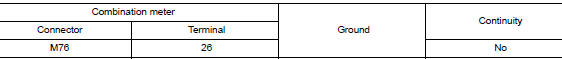
- Check continuity between combination meter harness connector M76 terminal 26 and ground.
Is the inspection result normal? YES >> Inspection End.
NO >> Repair or replace harness or connector.
Component Inspection
1.CHECK PARKING BRAKE SWITCH
Check continuity between parking brake switch terminal 1 and switch case ground.

Is the inspection result normal? YES >> Inspection End.
NO >> Replace parking brake switch. Refer to PB-7, "Exploded View".
 Fuel level sensor signal circuit
Component Function Check
1.COMBINATION METER INPUT SIGNAL
Select "METER/M&A" on "CONSULT".
Using "FUEL METER" of "Data Monitor", compare ...
 Ambient sensor signal circuit
Description
It detects outside air temperature and converts it into a resistance value
which is then input into the combination
meter.
Diagnosis Procedure
Regarding Wiring Diagram information, r ...
Other materials:
P0172 fuel injection system function
DTC Description
DTC DETECTION LOGIC
With the Air/Fuel Mixture Ratio Self-Learning Control, the actual mixture
ratio can be brought closely to the
theoretical mixture ratio based on the mixture ratio feedback signal from the
A/F sensors 1. The ECM calculates
the necessary compensation to corr ...
U1111 lost communication (chassis control module)
DTC Description
DTC DETECTION LOGIC
DTC
CONSULT screen terms
(Trouble diagnosis content)
DTC detection condition
U1111
LOST COMM (CHASSIS CONT MDUL)
(Lost Communication With Chassis Control
Module)
When the ignition switch is ON, TCM is unable to receive the CA ...
ECU diagnosis information
DIAGNOSIS SENSOR UNIT
DTC Index
DIAGNOSTIC CODE CHART
NOTE:
Follow the procedures in numerical order when repairing malfunctioning parts.
Confirm whether malfunction is
eliminated using air bag warning lamp or CONSULT each time repair is finished.
If malfunction is still
observed, proceed ...
