Nissan Rogue Service Manual: ECU diagnosis information
DIAGNOSIS SENSOR UNIT
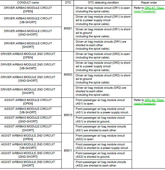
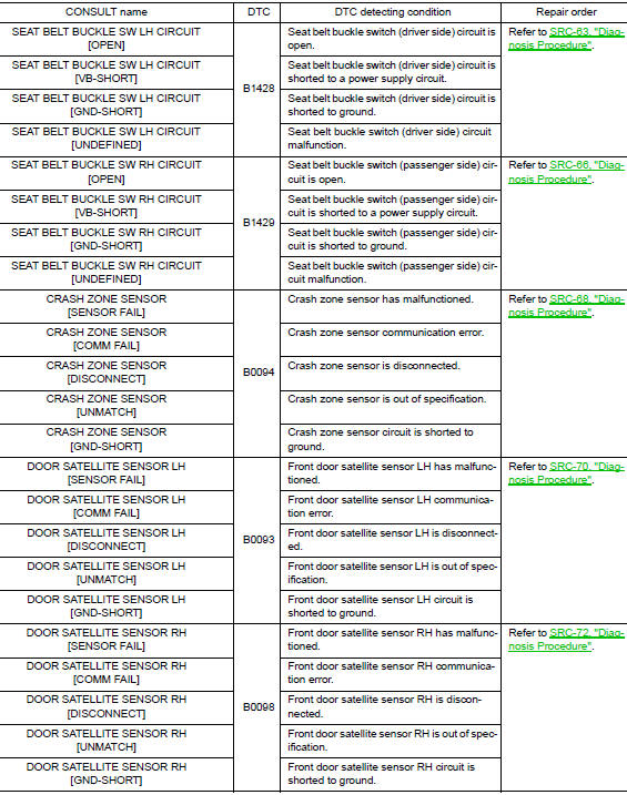
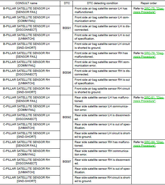
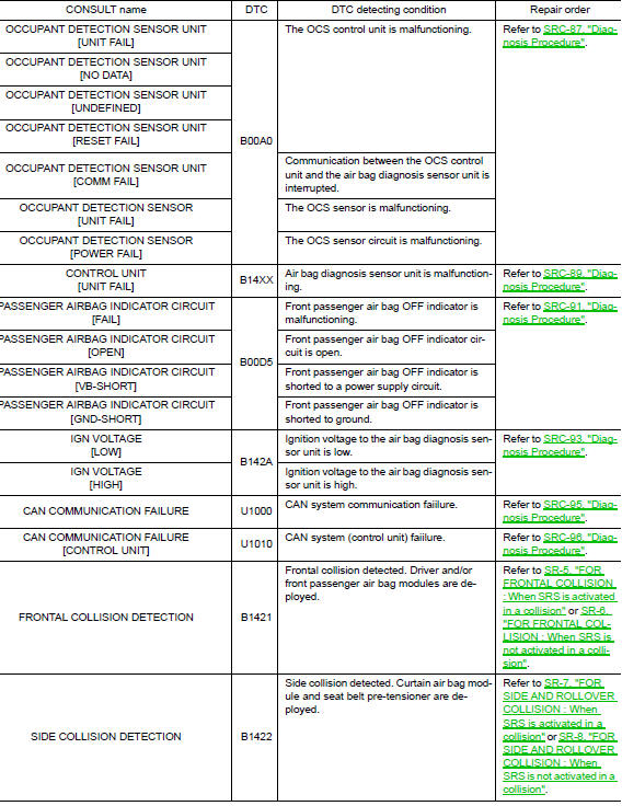
DTC Index
DIAGNOSTIC CODE CHART
NOTE: Follow the procedures in numerical order when repairing malfunctioning parts. Confirm whether malfunction is eliminated using air bag warning lamp or CONSULT each time repair is finished. If malfunction is still observed, proceed to the next step. When malfunction is eliminated, further repair work is not required.

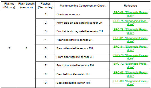
Flash Code Index
WARNING LAMP FLASH CODE CHART
- Put the vehicle in Diagnosis Mode. Refer to SRC-16, "On Board Diagnosis Function".
- All codes are proceded by a seven second "holding" flash.
- Identify how many primary flashes are displayed as well as the length of each primary flash.
- Refer to the tables and examples below to determine which SRS subsystem the code belongs to.
- Count the short secondary flashes that follow the primary flashes.
- Match the correct flashing pattern to the malfunctioning component and perform the Diagnosis Procedure.
Refer to the illustrations below for an example of each flashing pattern.
Front subsystem


Side subsystem


Air bag subsystem


Sensor subsystem
 Diagnosis system (air bag)
Description
CAUTION:
Never use electrical test equipment on any circuit related to
the SRS unless instructed in this Service
Manual. SRS wiring harnesses can be identified by yellow an ...
 Wiring diagram
SRS AIR BAG SYSTEM
Wiring Diagram
...
Other materials:
LATCH (Lower Anchors and Tethers for CHildren) System
LATCH system lower anchor locations - bench seat
Your vehicle is equipped with special anchor
points that are used with LATCH system compatible
child restraints. This system may also be
referred to as the ISOFIX or ISOFIX compatible
system. With this system, you do not have to use
a vehicl ...
U1111 lost communication (chassis control module)
DTC Description
DTC DETECTION LOGIC
DTC
CONSULT screen terms
(Trouble diagnosis content)
DTC detection condition
U1111
LOST COMM (CHASSIS CONT MDUL)
(Lost Communication With Chassis Control
Module)
When the ignition switch is ON, TCM is unable to receive the CA ...
C1734 BCM
DTC Logic
NOTE:
The Signal Tech II Tool [- (J-50190)] can be used to perform the following
functions. Refer to the Signal Tech II
User Guide for additional information.
Activate and display TPMS sensor IDs
Display tire pressure reported by the TPMS sensor
Read TPMS DTC ...
