Nissan Rogue Service Manual: Fuel level sensor signal circuit
Component Function Check
1.COMBINATION METER INPUT SIGNAL
- Select "METER/M&A" on "CONSULT".
- Using "FUEL METER" of "Data Monitor", compare the value of "Data Monitor" with fuel gauge pointer of combination meter.
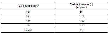
Does the data monitor value approximately match the fuel gauge indication? YES >> Inspection End.
NO >> Replace combination meter. Refer to MWI-82, "Removal and Installation".
Diagnosis Procedure
1.CHECK FUEL LEVEL SENSOR UNIT AND FUEL PUMP (FUEL LEVEL SENSOR) CIRCUIT
- Turn ignition switch OFF.
- Disconnect combination meter connector and fuel level sensor unit and fuel pump (fuel level sensor) connector.
- Check continuity between combination meter harness connector and fuel level sensor unit and fuel pump (fuel level sensor) harness connector.

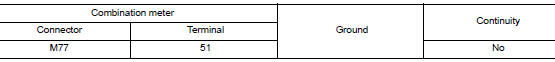
- Check continuity between combination meter harness connector and ground.
Is the inspection result normal? YES >> GO TO 2.
NO >> Repair harness or connector.
2.CHECK FUEL LEVEL SENSOR UNIT AND FUEL PUMP (FUEL LEVEL SENSOR) GROUND CIRCUIT
Check continuity between fuel level sensor unit and fuel pump (fuel level sensor) harness connector and combination meter harness connector.

Is the inspection result normal? YES >> Replace combination meter. Refer to MWI-82, "Removal and Installation".
NO >> Repair harness or connector.
Component Inspection
1.CHECK FUEL LEVEL SENSOR UNIT AND FUEL PUMP (FUEL LEVEL SENSOR)
- Remove the fuel level sensor unit and fuel pump (fuel level sensor). Refer to FL-6, "Removal and Installation".
- Check the resistance between fuel level sensor unit and fuel pump (fuel level sensor).
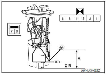
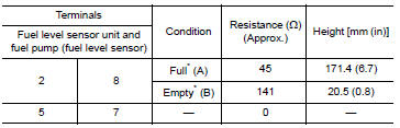
*: When float rod is contact with stopper.
Is the inspection result normal? YES >> GO TO 2.
NO >> Replace fuel level sensor unit and fuel pump (fuel level sensor). Refer to FL-6, "Removal and Installation".
2.CHECK FUEL LEVEL SENSOR UNIT (SUB)
- Remove the fuel level sensor unit (sub). Refer to FL-6, "Removal and Installation".
- Check the resistance between fuel level sensor unit (sub).


*: When float rod is contact with stopper.
Is the inspection result normal? YES >> Inspection End.
NO >> Replace fuel level sensor unit (sub). Refer to FL-6, "Removal and Installation".
 Power supply and ground circuit
COMBINATION METER
COMBINATION METER : Diagnosis Procedure
Regarding Wiring Diagram information, refer to MWI-32, "Wiring Diagram".
1.CHECK FUSES
Check that the following fuses are not bl ...
 Parking brake switch signal circuit
Description
Transmits the parking brake switch signal to the combination meter.
Component Function Check
1.COMBINATION METER INPUT SIGNAL
Start engine.
Check "PKB SW" in ...
Other materials:
How to use the remote keyless entry
function
The remote keyless entry function can operate all
door locks using the remote keyless function of
the Intelligent Key. The remote keyless function
can operate at a distance of 33 ft (10 m) away
from the vehicle. The operating distance depends
upon the conditions around the vehicle.
The remot ...
BSW system operation
BSW system operation
The BSW system operates above approximately
20 MPH (32 km/h).
When the camera unit detects vehicles in the
detection zone, the Blind Spot indicator light
located inside the outside mirrors will illuminate. If
the turn signal is then activated, the system
chimes (twi ...
P0138 HO2S2
DTC Description
DTC DETECTION LOGIC
The heated oxygen sensor 2 has a much longer switching time between rich and
lean than the air fuel ratio (A/
F) sensor 1. The oxygen storage capacity of the three way catalyst (manifold)
causes the longer switching
time.
MALFUNCTION A
To judge the malfu ...
