Nissan Rogue Service Manual: P0130 A/F sensor 1
DTC Description
DTC DETECTION LOGIC
To judge the malfunction, the diagnosis checks that the A/F signal computed by ECM from the A/F sensor 1 signal fluctuates according to fuel feedback control.
| DTC No. | CONSULT screen terms (Trouble diagnosis content) | DTC detecting condition | |
| P0130 | A/F SENSOR1 (B1) (O2 sensor circuit bank 1 sensor 1) | A | The A/F signal computed by ECM from the A/F sensor 1 signal is constantly in the range other than approx. 2.2 V. |
| B | The A/F signal computed by ECM from the A/F sensor 1 signal is constantly approx. 2.2 V. | ||
POSSIBLE CAUSE
- Harness or connectors (A/F sensor 1 circuit is open or shorted.)
- A/F sensor 1
FAIL-SAFE
Not applicable
DTC CONFIRMATION PROCEDURE
1.PRECONDITIONING
If DTC Confirmation Procedure has been previously conducted, always perform the following procedure before conducting the next test.
- Turn ignition switch OFF and wait at least 10 seconds.
- Turn ignition switch ON.
- Turn ignition switch OFF and wait at least 10 seconds.
TESTING CONDITION: Before performing the following procedure, confirm that battery voltage is more than 11 V at idle.
>> GO TO 2.
2.PERFORM DTC CONFIRMATION PROCEDURE FOR MALFUNCTION A
 With CONSULT
- Start engine and warm it up to normal operating temperature.
- Let it idle for 2 minutes.
- Check 1st trip DTC.
Is 1st trip DTC detected? YES >> Proceed to EC-227, "Diagnosis Procedure".
NO-1 >> With CONSULT: GO TO 3.
NO-2 >> Without CONSULT: GO TO 7.
3.CHECK AIR FUEL RATIO (A/F) SENSOR 1 FUNCTION
- Select “A/F SEN1 (B1)” in “DATA MONITOR” mode of “ENGINE” using CONSULT.
- Check “A/F SEN1 (B1)” indication.
Does the indication fluctuates around 2.2 V? YES >> GO TO 4.
NO >> Proceed to EC-227, "Diagnosis Procedure".
4.PERFORM DTC CONFIRMATION PROCEDURE FOR MALFUNCTION B-1
- Select “A/F SEN1 (B1) P1276” of “A/F SEN1” in “DTC WORK SUPPORT” mode of “ENGINE” using CONSULT.
- Touch “START”.
- When the following conditions are met, “TESTING” will be displayed on the CONSULT screen.
| ENG SPEED | 1,000 - 3,200 rpm |
| VHCL SPEED SE | More than 64 km/h (40 mph) |
| B/FUEL SCHDL | 1.0 - 8.0 msec |
| Selector lever | D position |
If “TESTING” is not displayed after 20 seconds, retry from step 2.
CAUTION: Always drive vehicle at a safe speed. Is “TESTING” displayed on CONSULT screen? YES >> GO TO 5.
NO >> Check A/F sensor 1 function again. GO TO 2.
5.PERFORM DTC CONFIRMATION PROCEDURE FOR MALFUNCTION B-2
Release accelerator pedal fully.
NOTE: Never apply brake during releasing the accelerator pedal. Which does “TESTING” change to? COMPLETED>>GO TO 6.
OUT OF CONDITION>>Retry DTC CONFIRMATION PROCEDURE. GO TO 3.
6.PERFORM DTC CONFIRMATION PROCEDURE FOR MALFUNCTION B-3
Touch “SELF-DIAG RESULT”
Which is displayed on CONSULT screen? YES >> INSPECTION END
NO >> Proceed to EC-227, "Diagnosis Procedure".
7.PERFORM COMPONENT FUNCTION CHECK FOR MALFUNCTION B
 With GST
- Start engine and warm it up to normal operating temperature.
- Drive the vehicle at a speed of 80 km/h (50 MPH) for a few minutes in the suitable gear position.
- Shift the selector lever to the D position, then release the
accelerator pedal fully until the vehicle speed
decreases to 50 km/h (31 MPH).
CAUTION: Always drive vehicle at a safe speed.
NOTE: Never apply brake during releasing the accelerator pedal.
- Repeat steps 2 to 3 for five times
- Stop the vehicle and turn ignition switch OFF.
- Wait at least 10 seconds and restart engine.
- Repeat steps 2 to 3 for five times.
- Stop the vehicle.
- Check 1st trip DTC.
Is 1st trip DTC detected? YES >> Proceed to EC-227, "Diagnosis Procedure".
NO >> INSPECTION END
Diagnosis Procedure
1.CHECK AIR FUEL RATIO (A/F) SENSOR 1 POWER SUPPLY
- Turn ignition switch OFF.
- Disconnect A/F sensor 1 harness connector.
- Turn ignition switch ON.
- Check the voltage between A/F sensor 1 harness connector and ground.

Is the inspection result normal? YES >> GO TO 3.
NO >> GO TO 2.
2.CHECK AIR FUEL RATIO (A/F) SENSOR 1 POWER SUPPLY CIRCUIT
- Turn ignition switch OFF.
- Disconnect IPDM E/R harness connector.
- Check the continuity between A/F sensor 1 harness connector and IPDM E/R harness connector.

- Also check harness for short to ground.
Is the inspection result normal? YES >> Perform the trouble diagnosis for power supply circuit.
NO >> Repair or replace error-detected parts.
3.CHECK A/F SENSOR 1 INPUT SIGNAL CIRCUIT
- Turn ignition switch OFF.
- Disconnect ECM harness connector.
- Check the continuity between A/F sensor 1 harness connector and ECM harness connector.

- Check the continuity between A/F sensor 1 harness connector and ground, or ECM harness connector and ground.
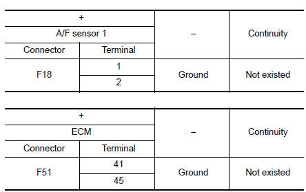
- Also check harness for short to power.
Is the inspection result normal?
YES >> GO TO 4.
NO >> Repair or replace error-detected parts.
4.CHECK INTERMITTENT INCIDENT
Perform GI-41, "Intermittent Incident".
Is the inspection result normal? YES >> GO TO 5.
NO >> Repair or replace error-detected parts.
5.REPLACE AIR FUEL RATIO (A/F) SENSOR 1
Replace air fuel ratio (A/F) sensor 1. Refer to EM-29, "Exploded View".
CAUTION:
- Discard any sensor which has been dropped from a height of more than 0.5 m (19.7 in) onto a hard surface such as a concrete floor; use a new one.
- Before installing new sensor, clean exhaust system threads using Oxygen Sensor Thread Cleaner [commercial service tool (J-43897-18 or J43897-12)] and approved Anti-seize Lubricant (commercial service tool).
>> INSPECTION END
 P0128 thermostat function
DTC Description
DTC DETECTION LOGIC
Engine coolant temperature has not risen enough to open the thermostat even
though the engine has run long
enough.
This is due to a leak in the seal or the ...
 P0131 A/F sensor 1
DTC Description
DTC DETECTION LOGIC
To judge the malfunction, the diagnosis checks that the A/F signal computed
by ECM from the A/F sensor 1
signal is not inordinately low.
DTC No.
CON ...
Other materials:
Headlight control switch
Type A (if so equipped)
When turning the switch to the
position,
the front parking, tail, license plate and
instrument panel lights come on.
When turning the switch to the
position,
the headlights come on and all the other
lights remain on.
Type B (if so equipped)
...
Seat belt warning system
Seat Belt Warning System Does Not Function
1.SEAT BELT WARNING LIGHT
Turn ignition switch ON.
Does the seat belt warning lamp come ON?
YES >> GO TO 2.
NO >>
Check 10A fuse [No. 13, located in the fuse block (J/B)].
Check seat belt buckle switch (driver seat).
...
Replacement operations
Description
This section is prepared for technicians who have attained a high level
of skill and experience in repairing
collision-damaged vehicles and also use modern service tools and equipment.
Persons unfamiliar with body
repair techniques should not attempt to repair collision-dam ...
