Nissan Rogue Service Manual: Replacement operations
Description
- This section is prepared for technicians who have attained a high level of skill and experience in repairing collision-damaged vehicles and also use modern service tools and equipment. Persons unfamiliar with body repair techniques should not attempt to repair collision-damaged vehicles by using this section.
- Technicians are also encouraged to read Body Repair Manual (Fundamentals) in order to ensure that the original functions and quality of the vehicle can be maintained. The Body Repair Manual (Fundamentals) contains additional information, including cautions and warning, that are not including in this manual. Technicians should refer to both manuals to ensure proper repairs.
- Please note that these information are prepared for worldwide usage, and as such, certain procedures might not apply in some regions or countries.
The symbols used in this section for welding operations are shown below.
|
Symbol marks |
Description |
|
 |
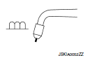
2-spot welds | 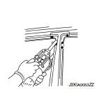 |
 |
3-spot welds |  |
 |
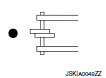
MIG plug weld |  |
 |
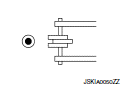
MIG seam weld / Point weld | |
- Front pillar butt joint can be determined anywhere within shaded area as shown in the figure. The best location for the butt joint is at position A due to the construction of the vehicle. Refer to the front pillar section.
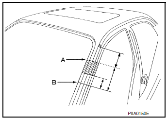
- Determine cutting position and record distance from the locating indent. Use this distance when cutting the service part. Cut outer front pillar over 60 mm (2.36 in) above inner front pillar cut position.

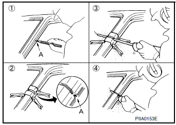
- Prepare a cutting jig to make outer pillar easier to cut. Also, this will permit service part to be accurately cut at joint position.

- An example of cutting operation using a cutting jig is as follows.
- Mark cutting lines.
- Cut position of outer pillar
- Cut position of inner pillar
- Align cutting line with notch on jig. Clamp jig to pillar.
- Cut outer pillar along groove of jig (at position A).
- Remove jig and cut remaining portions.
- Cut inner pillar at position B in same manner.
Hoodledge

Replacement parts
- Upper hoodledge (LH)
 Front
Front
Hoodledge Reinforcement
Replacement parts
- LH Hoodledge reinforcement
Front
Radiator Core Support Side

Replacement parts
- Radiator core support side
Front
Strut Housing
Replacement parts
- Strut housing
- Strut housing extension
Front
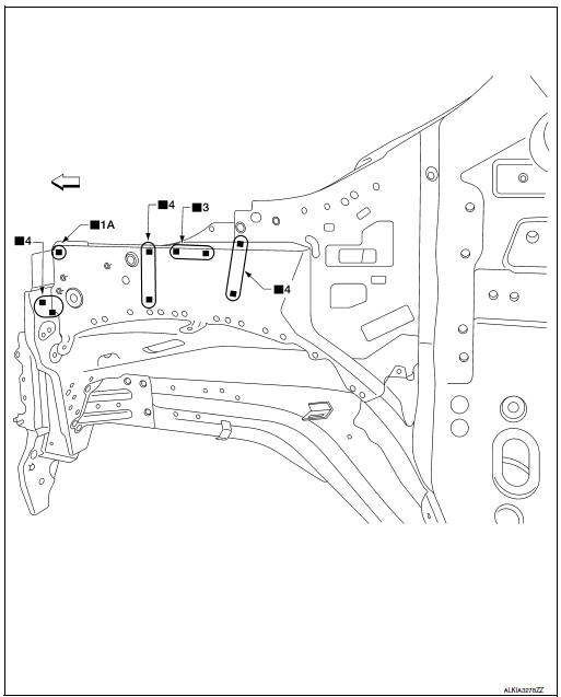
Front Side Member Outer
Work after hoodledge has been removed.

Replacement parts
- Front side member closing plate assembly (LH)
Front
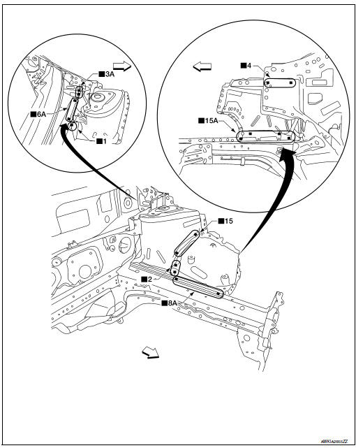
Front Side Member Inner
Work after hoodledge and strut housing has been removed.

Replacement parts
- Front side member inner assembly (LH)
Front
Front Side Member (Partial Replacement)
Replacement parts
- Front side member (RH)
- Front side member closing plate assembly (RH)
Front
Front Pillar
Work after hoodledge reinforcement has been removed.

Replacement parts
- Front side body (LH)
- Urethane foam
- Sectioning location
Front
View B: Before installing outer front side body

Replacement parts
- Inner front pillar reinforcement
- Urethane foam
Front
Center Pillar
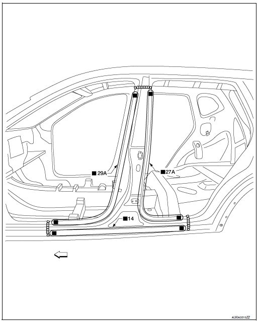
Replacement parts
- Outer center pillar
Front

Replacement parts
- Center pillar reinforcement
Front
Rear Fender

Replacement parts
- Rear fender assembly (LH)
- Urethane foam
Front
Rear Panel

Replacement parts
- Rear panel assembly
- Bolt
Front
Rear Floor Rear
Work after rear panel has been removed.

Replacement parts
- Rear floor rear
- Rear floor rear side
Front
Rear Side Member Extension
Work after rear panel has been removed.

Replacement parts
- Rear side member extension (LH)
Front
 Body construction
Body Construction
Outer body side
Outer front pillar reinforcement
Upper inner front pillar
Rear hoodledge reinforcement
Side dash
Inner front pillar reinforcement
Lower ...
 Service data and specifications (SDS)
BODY ALIGNMENT
Body Center Marks
mark has been placed on each part of the body to indicate the vehicle center.
When repairing parts damaged
by an accident which might affect the vehicle frame (me ...
Other materials:
P0507 ISC system
Description
The ECM controls the engine idle speed to a specified level through the fine
adjustment of the air, which is let
into the intake manifold, by operating the electric throttle control actuator.
The operating of the throttle valve is
varied to allow for optimum control of the engine ...
Power panoramic moonroof (if so equipped)
The moonroof will only operate when the ignition
switch is placed in the ON position. The moonroof
is operational for a period of time, even if the
ignition switch is placed in the ACC (if so
equipped) or OFF position. If the driverŌĆÖs door or
the front passengerŌĆÖs door is opened during ...
C1155 brake fluid level switch
DTC Logic
DTC DETECTION LOGIC
DTC
Display Item
Malfunction detected condition
Possible causes
C1155
BR FLUID LEVEL LOW
When brake fluid level low signal is detected
Harness or connector
ABS actuator and electric unit
(control unit)
...
