Nissan Rogue Service Manual: P0340 CMP sensor (phase)
DTC Description
DTC DETECTION LOGIC
| DTC No. | CONSULT screen terms (Trouble diagnosis content) | DTC detecting cond |
| P0340 | CMP SEN/CIRC-B1 (Camshaft position sensor ″A″ circuit bank 1 or single sensor) |
|
POSSIBLE CAUSE
- Harness or connectors (Camshaft position sensor circuit is open or shorted.)
- Camshaft position sensor
- Camshaft (Intake)
- Starter motor
- Starting system circuit
- Dead (Weak) battery
- Sensor power supply 2 circuit
FAIL-SAFE
Not applicable
DTC CONFIRMATION PROCEDURE
1.PRECONDITIONING
If DTC Confirmation Procedure has been previously conducted, always perform the following procedure before conducting the next test.
- Turn ignition switch OFF and wait at least 10 seconds.
- Turn ignition switch ON.
- Turn ignition switch OFF and wait at least 10 seconds.
TESTING CONDITION: Before performing the following procedure, confirm that battery voltage is more than 10.5 V with ignition switch ON.
>> GO TO 2.
2.PERFORM DTC CONFIRMATION PROCEDURE-1
- Start engine and let it idle for at least 5 seconds.
If engine does not start, crank engine for at least 2 seconds.
- Check 1st trip DTC.
Is 1st trip DTC detected? YES >> Proceed to EC-298, "Diagnosis Procedure".
NO >> GO TO 3.
3.PERFORM DTC CONFIRMATION PROCEDURE-2
- Maintaining engine speed at more than 800 rpm for at least 5 seconds.
- Check 1st trip DTC.
Is 1st trip DTC detected? YES >> Proceed to EC-298, "Diagnosis Procedure".
NO >> INSPECTION END
Diagnosis Procedure
1.CHECK STARTING SYSTEM
Turn ignition switch to START position.
Does the engine turn over? Does the starter motor operate?
YES >> GO TO 2.
NO >> Check starting system (Refer to STR-11, "Work Flow (With GR8-1200 NI)" or STR-15, "Work Flow (Without GR8-1200 NI)").
2.CHECK CAMSHAFT POSITION (CMP) SENSOR (PHASE) POWER SUPPLY
- Turn ignition switch OFF.
- Disconnect camshaft position (CMP) sensor (PHASE) harness connector.
- Turn ignition switch ON.
- Check the voltage between CMP sensor (PHASE) harness connector and ground.
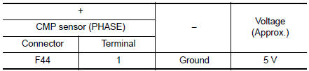
Is the inspection result normal? YES >> GO TO 4.
NO >> GO TO 3.
3.CHECK SENSOR POWER SUPPLY 2 CIRCUIT
Perform EC-484, "Diagnosis Procedure".
Is inspection result normal? YES >> Perform the trouble diagnosis for power supply circuit.
NO >> Repair or replace error-detected parts.
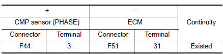
4.CHECK CMP SENSOR (PHASE) GROUND CIRCUIT
- Turn ignition switch OFF.
- Disconnect ECM harness connector.
- Check the continuity between CMP sensor (PHASE) harness connector and ECM harness connector.

- Also check harness for short to power.
Is the inspection result normal? YES >> GO TO 5.
NO >> Repair or replace error-detected parts.
5.CHECK CMP SENSOR (PHASE) INPUT SIGNAL CIRCUIT
- Disconnect ECM harness connector.
- Check the continuity between CMP sensor (PHASE) harness connector and ECM harness connector
- Also check harness for short to ground and to power.
Is the inspection result normal? YES >> GO TO 6.
NO >> Repair or replace error-detected parts.
6.CHECK CAMSHAFT POSITION SENSOR (PHASE)
Check the camshaft position sensor (PHASE). Refer to EC-300, "Component Inspection (Camshaft position sensor)".
Is the inspection result normal? YES >> GO TO 7.
NO >> Replace camshaft position sensor (PHASE). Refer to EM-64, "Removal and Installation".
7.CHECK CAMSHAFT (INT)
Check the following.
- Accumulation of debris to the signal plate of camshaft rear end
- Chipping signal plate of camshaft rear end
Is the inspection result normal? YES >> GO TO 8.
NO >> Remove debris and clean the signal plate of camshaft rear end or replace camshaft. Refer to EM-64, "Removal and Installation".

8.CHECK INTERMITTENT INCIDENT
Refer to GI-41, "Intermittent Incident".
>> INSPECTION END
Component Inspection (Camshaft position sensor)
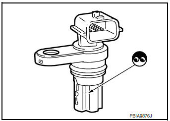
1.CHECK CAMSHAFT POSITION SENSOR (PHASE)-1
- Turn ignition switch OFF.
- Loosen the fixing bolt of the sensor.
- Disconnect camshaft position sensor (PHASE) harness connector.
- Remove the sensor.
- Visually check the sensor for chipping.
Is the inspection result normal? YES >> GO TO 2.
NO >> Replace camshaft position sensor (PHASE).
2.CHECK CAMSHAFT POSITION SENSOR (PHASE)-2
Check the resistance camshaft position sensor (PHASE) terminals as per the following.

Is the inspection result normal? YES >> INSPECTION END
NO >> Replace camshaft position sensor (PHASE). Refer to EM-64, "Removal and Installation".
 P0335 CKP sensor (POS)
DTC Description
DTC DETECTION LOGIC
DTC No.
CONSULT screen terms
(Trouble diagnosis content)
DTC detecting conditio
P0335
CKP SEN/CIRCUIT
(Crankshaft position sensor & ...
 P0420 three way catalyst function
DTC Description
DTC DETECTION LOGIC
The ECM monitors the switching frequency ratio of air fuel ratio (A/F)
sensor 1 and heated oxygen sensor 2.
A three way catalyst (manifold) with high oxygen s ...
Other materials:
Uniform tire quality grading
DOT (Department of Transportation) Quality
Grades: All passenger car tires must conform to
federal safety requirements in addition to these
grades.
Quality grades can be found where applicable on
the tire sidewall between tread shoulder and
maximum section width. For example:
Treadwear 200 ...
U1050, U1051 LIN communication
DTC Description
DTC DETECTION LOGIC
DTC No.
CONSULT screen terms
(Trouble diagnosis content)
DTC detecting condition
U1050
LIN COMMUNICATION
[LIN (Local Interconnect Network) communication)]
ECM detects LIN communication error.
U1051
POSSIBLE CAUSE
...
Front wiper motor HI circuit
Component Function Check
1.CHECK FRONT WIPER HI OPERATION
CONSULT ACTIVE TEST
Select FR WIPER of BCM (WIPER) active test item.
Check front wiper operation.
HI : Front wiper (HI) operation
OFF : Front wiper OFF
Is the inspection result normal?
YES >> Front wiper motor ...
