Nissan Rogue Service Manual: Rear washer nozzle and tube
Exploded View

- Rear washer tube
- Rear grommet
 Clip
Clip
Removal and Installation - Rear Washer Nozzle
REMOVAL
- Remove rear access panel. Refer to INT-38, "Exploded View".
- Release pawls and remove rear washer nozzle (1).
 : Pawl

INSTALLATION
Installation in the reverse order of removal.
Removal and Installation - Rear Washer Tube
REMOVAL
- Remove engine side cover (RH). Refer to EXT-28, "FENDER PROTECTOR : Exploded View".
- Release clips and remove front air spoiler.
- Remove engine under cover. Refer to EXT-37, "ENGINE UNDER COVER : Removal and Installation".
- Partially remove fender protector (RH). Refer to EXT-37, "ENGINE UNDER COVER : Removal and Installation".
- Release seat latches by pulling straps (A) rearward, then lift seat from seat strikers (LH/RH).

- Remove dash side finisher (RH). Refer to INT-24, "DASH SIDE FINISHER : Removal and Installation".
- Remove center pillar lower finisher (RH). Refer to INT-22, "CENTER PILLAR LOWER FINISHER : Removal and Installation".
- Remove luggage rear plate. Refer to INT-37, "LUGGAGE REAR PLATE : Removal and Installation".
- Remove luggage side upper finisher (LH/RH). Refer to INT-36, "LUGGAGE SIDE UPPER FINISHER : Removal and Installation".
- Release rear clips and partially remove headliner. Refer to INT-29, "Exploded View".
- Disconnect rear washer tube from washer tank and rear washer nozzle.
- Release clips and remove rear washer tube.
INSTALLATION
Installation is in the reverse order of removal.
Inspection and Adjustment
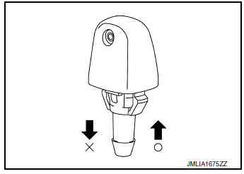
INSPECTION
Check that air can pass through the nozzle by blowing into the nozzle and that air cannot flow in the opposite direction.
O: Air can go
X: Air cannot go
ADJUSTMENT
If operating properly, spray positions should match the positions shown. If spray positions do not match, confirm the rear washer nozzle is properly seated and working properly. If the spray positions still do not match as shown, then replace the rear washer nozzle. Refer to WW-72, "Removal and Installation - Rear Washer Nozzle"
- Black print
- Wiping area
- Spray target area
- 12.8
- 12.8
- 25.7
- 15.6
- 20.6
 Rear wiper motor
Exploded View
Rear wiper motor
Back door
Rear wiper motor harness
Removal and Installation
REMOVAL
Remove rear wiper arm. Refer to WW-69, "Removal and Installation&quo ...
 Service data and specifications (sds)
Specifications
WINDSHIELD WASHER FLUID
...
Other materials:
Service data and specifications (SDS)
General Specifications
Preload Torque
Drive Gear Runout
Backlash
Differential Side Gear Clearance
...
Filament
Inspection and Repair
INSPECTION
When measuring voltage, wrap tin foil around the top of the
negative
probe. Then press the foil against the wire with your finger.
Attach probe circuit tester (in Volt range) to middle portion of
each filament.
If a filament is b ...
Air bag diagnosis sensor unit
Exploded View
Diagnosis sensor unit
Front
Removal and Installation
WARNING:
Before servicing the SRS, turn ignition switch OFF, disconnect
both battery terminals then wait at
least three minutes.
Before disconnecting the air bag diagnosis sensor unit harness
...