Nissan Rogue Service Manual: Power supply and ground circuit
COMBINATION METER
COMBINATION METER : Diagnosis Procedure
Regarding Wiring Diagram information, refer to MWI-32, "Wiring Diagram".
1.CHECK FUSES
Check that the following fuses are not blown.

Is the fuse blown? YES >> Replace the blown fuse after repairing the affected circuit.
NO >> GO TO 2.
2.POWER SUPPLY CIRCUIT CHECK
1. Disconnect combination meter connector.
2. Check voltage between combination meter harness connector M77 terminals 45, 46 and ground.
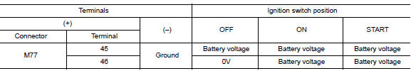
Is the inspection result normal? YES >> GO TO 3.
NO >> Repair or replace harness or connector.
3.GROUND CIRCUIT CHECK
- Turn ignition switch OFF.
- Check continuity between combination meter harness connector and ground.

Is the inspection result normal? YES >> Inspection End.
NO >> Repair or replace harness or connector.
BCM (BODY CONTROL SYSTEM) (WITH INTELLIGENT KEY SYSTEM)
BCM (BODY CONTROL SYSTEM) (WITH INTELLIGENT KEY SYSTEM) : Diagnosis Procedure
Regarding Wiring Diagram information, refer to BCS-50, "Wiring Diagram".
1. CHECK FUSE
Check that the following fuse is not blown.

Is the fuse blown? YES >> Replace the blown fuse after repairing the affected circuit.
NO >> GO TO 2.
2. CHECK POWER SUPPLY CIRCUIT
- Disconnect BCM connector M20.
- Check voltage between BCM connector M20 and ground.

Is the inspection result normal? YES >> GO TO 3.
NO >> Repair or replace harness or connectors.
3. CHECK GROUND CIRCUIT
Check continuity between BCM connector M20 and ground.

Is the inspection result normal? YES >> Inspection End.
NO >> Repair or replace harness or connectors.
BCM (BODY CONTROL SYSTEM) (WITHOUT INTELLIGENT KEY SYSTEM)
BCM (BODY CONTROL SYSTEM) (WITHOUT INTELLIGENT KEY SYSTEM) : Diagnosis Procedure
Regarding Wiring Diagram information, refer to BCS-110, "Wiring Diagram".
1. CHECK FUSE
Check that the following fuse is not blown.

Is the fuse blown? YES >> Replace the blown fuse after repairing the affected circuit.
NO >> GO TO 2.
2. CHECK POWER SUPPLY CIRCUIT
- Disconnect BCM connector M20.
- Check voltage between BCM connector M20 and ground.

Is the inspection result normal? YES >> GO TO 3.
NO >> Repair or replace harness or connectors.
3. CHECK GROUND CIRCUIT
Check continuity between BCM connector M20 and ground.

Is the inspection result normal? YES >> Inspection End.
NO >> Repair or replace harness or connectors.

 Meter buzzer circuit
Description
The buzzer for the warning chime system is installed in the combination
meter.
The combination meter sounds the buzzer based on the signals transmitted
from various units.
C ...
Other materials:
Specifications
Engine
Model
QR25DE
Type
Gasoline, 4-cycle, DOHC
Cylinder arrangement
4-cylinder
Bore x Stroke
in (mm)
3.5 x 3.9 (89.0 x 100.0)
Displacement
cu in (cm3)
151.82 (2,488)
Firing order
1-3-4-2
Idle speed
No ...
Consult/gst checking system
Description
NOTE:
This vehicle is diagnosed using the CONSULT-III plus.
When CONSULT is connected with a data link connector equipped
on the vehicle side, it will communicate with the control unit
equipped in the vehicle and then enable various kinds of diagnostic
tests.
Ho ...
Front seat
Exploded View
DRIVER POWER SEAT
Headrest
Seatback support
Seatback board
Seatback heater (if equipped)
Seatback trim
Seatback pad
Seat cushion outer finisher (RH)
Seat cushion rear finisher
(RH)
Seat cushion inner finisher (RH)
Seat sli ...
