Nissan Rogue Service Manual: Main power supply and ground circuit
Diagnosis Procedure
1.CHECK TCM POWER CIRCUIT (PART 1)
- Turn ignition switch OFF.
- Disconnect TCM connector.
- Check voltage between TCM harness connector terminals and ground.
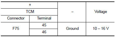
Is the inspection result normal? YES >> GO TO 2.
NO >> GO TO 4.
2.CHECK TCM POWER CIRCUIT (PART 2)
Check voltage between TCM harness connector terminals and ground.

Is the inspection result normal? YES >> GO TO 3.
NO >> GO TO 5.
3.CHECK TCM GROUND CIRCUIT
Check continuity between TCM harness connector terminals and ground.

Is the inspection result normal? YES >> Check intermittent incident. Refer to GI-41, "Intermittent Incident".
NO >> Repair or replace malfunctioning parts.
4.DETECT MALFUNCTION ITEMS (PART 1)
Check the following items:
- Open circuit or short circuit in harness between battery positive terminal and TCM connector terminal 45, and 46.
- 10A fuse (No.59, located in the fuse and fusible link block). Refer to PG-65, "Terminal Arrangement".
Is the inspection result normal? YES >> Check intermittent incident. Refer to GI-41, "Intermittent Incident".
NO >> Repair or replace malfunctioning parts.
5.CHECK CIRCUIT BETWEEN IPDM E/R AND TCM
- Turn ignition switch OFF.
- Disconnect IPDM E/R connector.
- Check continuity between IPDM E/R harness connector terminal and TCM harness connector terminals.

Is the check result normal? YES >> GO TO 6.
NO >> Repair or replace malfunctioning parts.
6.DETECT MALFUNCTIONING ITEMS (PART 2)
Check the following items:
- Open circuit or short circuit in harness between ignition switch and IPDM E/R. Refer to PG-15, "Wiring Diagram — Ignition Power Supply —".
- Short circuit in harness between IPDM E/R harness connector terminal 70 and TCM harness connector terminals 47, and 48.
- 10A fuse (No.46, located in the IPDM E/R). Refer to PG-68, "IPDM E/R Terminal Arrangement".
- IPDM E/R
Is the check result normal? YES >> Check intermittent incident. Refer to GI-41, "Intermittent Incident".
NO >> Repair or replace malfunctioning parts.
 P2815 select solenoid
DTC Description
DTC DETECTION LOGIC
DTC
CONSULT screen terms
(Trouble diagnosis content)
DTC detection condition
P2815
SELECT SOLENOID
(Select solenoid)
When all of ...
 Overdrive control switch
Component Function Check
1.CHECK O/D OFF INDICATOR LAMP FUNCTION
Check O/D OFF indicator lamp turns ON for approx. 2 seconds when ignition
switch turns ON.
Is the inspection results normal?
YE ...
Other materials:
Ignition signal
Component Function Check
1.INSPECTION START
Turn ignition switch OFF, and restart engine.
Does the engine start?
YES-1 >> With CONSULT: GO TO 2.
YES-2 >> Without CONSULT: GO TO 3.
NO >> Proceed to EC-470, "Diagnosis Procedure".
2.CHECK IGNITION SIGNAL FUNCTIO ...
System
EPS SYSTEM
EPS SYSTEM : System Description
SYSTEM DIAGRAM
INPUT/OUTPUT SIGNAL
Communicates the signal from each control unit via CAN communication.
Control unit
Signal status
ECM
Transmits the following signal to EPS control unit via CAN
communica ...
Power generation voltage variable control system operation
inspection
Diagnosis Procedure
Regarding Wiring Diagram information. Refer to CHG-7, "Wiring Diagram".
CAUTION:
When performing this inspection, always use a charged battery that has completed
the battery inspection.
(When the charging rate of the battery is low, the response speed of the vol ...
