Nissan Rogue Service Manual: Intake manifold
Exploded View

- Intake manifold
- Intake manifold gasket
- Electirc throttle control actuator O-ring
- Electric throttle control actuator
Removal and Installation
REMOVAL
WARNING: To avoid danger of being scalded, do not drain engine coolant when engine is hot.
NOTE: When removing components such as hoses, tubes/lines, etc., cap or plug openings to prevent fluid from spilling.
- Disconnect battery negative terminal.
- Remove the air cleaner and air duct. Refer to EM-24, "Removal and Installation".
- Disconnect the PCV hose from the rocker cover.
- Disconnect harness connector from EVAP canister purge volume control solenoid.
- Disconnect the EVAP hose and EVAP canister purge volume control solenoid.
- Disconnect the brake booster vacuum hose from the intake manifold.
- Disconnect harness connector from electric throttle control actuator.
- Disconnect the water hoses from the electric throttle control actuator (if necessary).
CAUTION:
- Do not allow the engine coolant to contact the drive belt.
- Perform this step when engine is cold.
NOTE:
When removing only intake manifold, position electric throttle control actuator aside without disconnecting the water hose.
- Loosen bolts in reverse order as shown, then remove electric throttle control actuator and electric throttle control actuator Oring.
CAUTION:
- Handle carefully to avoid any damage.
- Cover intake manifold opening to prevent entry of foreign materials.

- Remove front exhaust tube. Refer to EX-5, "Exploded View".
- Disconnect harness connector from intake manifold runner control valve.
- Disconnect harness connector from intake manifold runner control valve position sensor.
- Remove harness retainers.
- Remove intake manifold in the reverse order shown and remove the intake manifold gasket.
CAUTION: Cover engine openings to prevent entry of foreign materials.
INSTALLATION
Installation is in the reverse order of removal. Follow the tightening sequences and specifications below and perform the following:
- Add engine coolant (if necessary). Refer to CO-9, "Refilling".
- Perform the “Throttle Valve Closed Position Learning” when harness connector of electric throttle control actuator is disconnected. Refer to EC-140, "Work Procedure".
- Perform the “Idle Air Volume Learning” and “Throttle Valve Closed Position Learning” when electric throttle control actuator is replaced. Refer to EC-141, "Work Procedure" or EC-140, "Work Procedure".
Intake Manifold
- Securely install gasket to groove.
CAUTION: Do not reuse gasket.
- If studs were removed, install them and tighten to specification.
Studs : 9.4 N·m (0.96 kg-m, 83 in-lb)
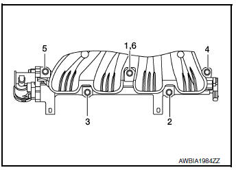
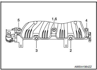
- Tighten in numerical order as shown.
CAUTION: After tightening the five bolts in the order shown, the 1, 6 position designates that the first bolt tightened is to be retightened to specification.
Nuts/Bolts 1, 2, 3, 4, 5, 6 : 25 N·m (2.6 kg-m, 18 ft-lb)
Electric Throttle Control Actuator
- Install a new O-ring on the electric throttle control actuator.
CAUTION: Do not reuse electric throttle control actuator O-ring.
- Tighten the bolts of electric throttle control actuator equally and diagonally in several steps in numerical order as shown.

INSPECTION AFTER INSTALLATION
Make sure there are no fuel leaks at connections as follows:
- Apply fuel pressure to fuel lines by turning ignition switch ON
(with engine stopped). Then check for fuel
leaks at connections.
NOTE: Use mirrors for checking on connections out of the direct line of sight.
- Start the engine and rev it up and check for fuel leaks at
connections.
WARNING: Do not touch engine immediately after stopping as engine is extremely hot.
 Air cleaner and air duct
Exploded View
Mass air flow sensor
Air cleaner filter
Air cleaner case (lower)
Air duct assembly
Grommet
Resonator bracket (front)
Resonator bracket (rear)
...
 Exhaust manifold and three way
catalyst
Exhaust manifold and three way
catalyst
Exploded View
Cylinder head
Exhaust manifold and three way
catalyst gasket
Exhaust manifold cover (upper)
Exhaust manifold and three way catalyst
Exhaust manifold ...
Other materials:
How to select piston and bearing
DESCRIPTION
Selection points
Selection parts
Selection items
Selection methods
Between cylinder block to
crankshaft
Main bearing
Main bearing grade (bearing
thickness)
Determined by match of cylinder
block bearing housing
grade (inner diameter of housin ...
Front passenger air bag module
Exploded View
Front passenger air bag module
Steering member
Removal and Installation
WARNING:
Before servicing the SRS, turn ignition switch OFF, disconnect
both battery terminals then wait at
least three minutes.
Always work from the side of air bag module. Do ...
Periodic maintenance
REAR PROPELLER SHAFT
Inspection
APPEARANCE AND NOISE
Check the propeller shaft tube surface for dents or cracks. If
malfunction is detected, replace propeller shaft
assembly.
If center bearing is noisy or damaged, replace propeller shaft
assembly.
VIBRATION
If vibrati ...
