Nissan Rogue Service Manual: Electrical load signal
Description
The electrical load signal (Headlamp switch signal, rear window defogger switch signal, etc.) is transferred via the CAN communication.
Component Function Check
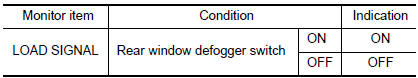
1.CHECK REAR WINDOW DEFOGGER SWITCH FUNCTION
- Turn ignition switch ON.
- Connect CONSULT and select ÔÇťDATA MONITORÔÇŁ mode.
- Select ÔÇťLOAD SIGNALÔÇŁ and check indication under the following conditions.
Is the inspection result normal? YES >> GO TO 2.
NO >> Proceed to EC-462, "Diagnosis Procedure".
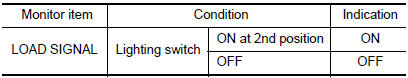
2.CHECK LIGHTING SWITCH FUNCTION
Check ÔÇťLOAD SIGNALÔÇŁ indication under the following conditions.
Is the inspection result normal? YES >> GO TO 3.
NO >> Proceed to EC-462, "Diagnosis Procedure".
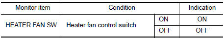
3.CHECK HEATER FAN CONTROL SWITCH FUNCTION
Select ÔÇťHEATER FAN SWÔÇŁ and check indication under the following conditions.
Is the inspection result normal? YES >> INSPECTION END
NO >> Proceed to EC-462, "Diagnosis Procedure".
Diagnosis Procedure
1.INSPECTION START
Confirm the malfunctioning circuit (rear window defogger, headlamp or heater fan). Refer to EC-462, "Component Function Check".
Which circuit is related to the incident? Rear window defogger>>GO TO 2.
Headlamp>>GO TO 3.
Heater fan>>GO TO 4.
2.CHECK REAR WINDOW DEFOGGER SYSTEM
Check rear window defogger system. Refer to DEF-19, "Work Flow".
>> INSPECTION END
3.CHECK HEADLAMP SYSTEM
Check headlamp system. Refer to EXL-82, "Work Flow" (with halogen headlamp) or EXL-219, "Work Flow" (with LED headlamp).
>> INSPECTION END
4.CHECK HEATER FAN CONTROL SYSTEM
Check heater fan control system. Refer to HAC-46, "Work Flow" (with automatic air conditioner) or HAC-146, "Work Flow" (with manual air conditioner).
>> INSPECTION END
 Cooling fan
Component Function Check
1.CHECK COOLING FAN FUNCTION
With CONSULT
Turn ignition switch ON.
Perform ÔÇťCOOLING FAN (DUAL)ÔÇŁ in ÔÇťACTIVE TESTÔÇŁ mode of ÔÇťIPDM E/RÔÇŁ
using CO ...
 Fuel injector
Component Function Check
1.INSPECTION START
Turn ignition switch to START.
Are any cylinders ignited?
YES >> GO TO 2.
NO >> Proceed to EC-464, "Diagnosis Procedure".
2. ...
Other materials:
P1225 TP sensor
DTC Description
DTC DETECTION
DTC No.
CONSULT screen terms
(Trouble diagnosis content)
DTC detecting condition
P1225
CTP LEARNING-B1
(CTP LEARNING-B1)
Closed throttle position learning value is excessively low.
POSSIBLE CAUSE
Electric throttle control actua ...
Changing wheels and tires
Tire rotation
NISSAN recommends rotating the tires
every 7,500 miles (12,000 km).
Refer to ÔÇťFlat tireÔÇŁ in the ÔÇťIn case of emergencyÔÇŁ
section in this manual for tire replacing
procedures.
As soon as possible, tighten the
wheel nuts to the specified torque
with a torque wrench.
...
Engine maintenance
DRIVE BELTS
DRIVE BELTS : Exploded View
Generator pulley
Water pump pulley
Drive belt auto-tensioner
Crankshaft pulley
A/C compressor pulley
Drive belt retainer boss
View A
New drive belt range
Possible use range
Indicator (notch)
DRIVE BELTS : C ...
