Nissan Rogue Service Manual: Control cable
Exploded View
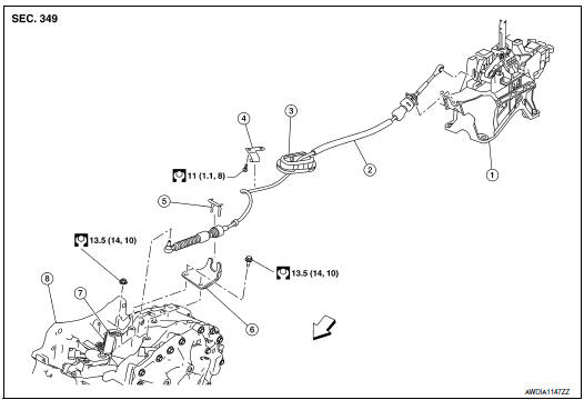
- Shift selector
- Control cable
- Retainer grommet
- Lock plate
- Bracket
- Manual lever
- Transaxle assembly
 Front
Front
Removal and Installation
CAUTION: Always apply the parking brake before performing removal and installation.
REMOVAL
- Apply the parking brake.
CAUTION: Make sure the vehicle cannot move with the parking brake applied.
- Remove battery tray. Refer to PG-76, "Removal and Installation (Battery Tray)".
- Remove the control cable nut (
 ) and remove the control cable
(1) from the manual lever (2).
) and remove the control cable
(1) from the manual lever (2).

 : Front
- Remove the lock plate (1) and remove the control cable (2) from bracket (3).

: Front
- Remove the center console assembly. Refer to IP-18, "Removal and Installation".
- Disconnect the tip (A) of control cable and remove the socket (B) from the CVT shift selector assembly.

- Remove the control cable (1) from bracket (2).
- Remove by pushing retainer grommet (3) upward.

: Front
- Remove the control cable.
INSTALLATION
Installation is in the reverse order of removal.
- Pay attention to the following when connecting the control cable to the CVT shift selector assembly.
- When connecting the control cable (1) to the CVT shift selector
assembly (2), face the grooved surface of the rib (A) up and
insert the control cable until it stops.
NOTE: Apply multi-purpose grease to control cable eye before installation.

- Install the socket (A) onto the CVT shift selector assembly.
CAUTION:
- Place the socket onto the CVT shift selector assembly, then fasten it in place from above.
- Check that the pulling on the socket does not disconnect it.

Inspection and Adjustment
ADJUSTMENT AFTER INSTALLATION
Adjust the CVT position. Refer to TM-92, "Adjustment".
INSPECTION AFTER ADJUSTMENT
Check the CVT shift selector position after the adjustment. Refer to TM-92, "Inspection".
 CVT shift selector
Exploded View
Shift selector knob
Lock pin
Shift selector assembly
Control cable
Shift selector knob cover
Front
Removal and installation
REMOVAL
Apply the parking b ...
 Key interlock cable
Exploded View
Key cylinder
Clip
Key interlock cable
Shift selector assembly
Removal and Installation
REMOVAL
CAUTION:
Always apply the parking brake before perf ...
Other materials:
Component parts
Component Parts Location
A/C switch (auto A/C)
Front air control (manual A/C)
No.
Component
Description
1
Rear window defogger connector
(Rear window defogger)
Refer to DEF-5, "Rear window defogger".
2
3
Rear win ...
DTC/circuit diagnosis
U0121 VDC CAN 2
DTC Logic
DTC DETECTION LOGIC
NOTE:
If DTC U0121 is displayed with DTC U1000, first perform the trouble diagnosis
for DTC U1000. Refer to DAS-
106, "DISTANCE SENSOR : DTC Logic".
CONSULT Display
DTC Detection Condition
Possible Cause
...
Personal lamp
Removal and Installation
The personal lamp is serviced as part of headlining. Refer to INT-30,
"Removal and Installation".
Bulb or Lens Replacement
WARNING:
Do not touch the glass surface of a bulb while it is lit or right after being
turned OFF to prevent burns.
CAUTION:
&n ...
