Nissan Rogue Service Manual: ABS actuator and electric unit (control unit)
Exploded View
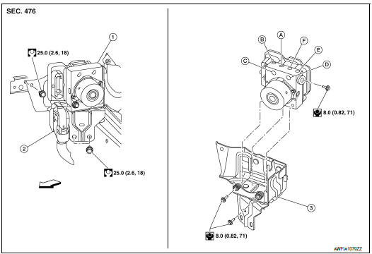
- ABS actuator and electric unit (control unit)
- Connector
- Bracket
- To front LH brake caliper
- To rear RH brake caliper
- From master cylinder secondary side
- From master cylinder primary side
- To rear LH brake caliper
- To front RH brake caliper
Removal and Installation
REMOVAL
CAUTION:
- To remove brake tube, use a flare nut wrench to prevent flare nuts and brake tube from being damaged.
- Do not remove actuator by holding harness.
NOTE: When removing components such as hoses, tubes/lines, etc., cap or plug openings to prevent fluid from spilling.
- Disconnect negative battery terminal. Refer to PG-75, "Exploded View".
- Remove the cowl top cover and cowl top extension. Refer to EXT-25, "Removal and Installation".
- Separate brake tubes from ABS actuator and electric unit (control unit). Refer to BR-22, "FRONT : Exploded View".
- Remove the brake booster vacuum hose. Refer to BR-32, "Removal and Installation".
- Separate the brake booster vacuum tube and place aside. Refer to BR-23, "FRONT : Removal and Installation".
- Disconnect the harness connector from the ABS actuator and electric unit (control unit).
- Remove ABS actuator and electric unit (control unit) bracket bolts and bushings.
- Remove ABS actuator and electric unit (control unit) from vehicle.
INSTALLATION
Installation is in the reverse order of removal.
- After work is completed, bleed air from brake tube. Refer to BR-16, "Bleeding Brake System".
- Adjust the neutral position of steering angle sensor. Refer to BRC-70, "Work Procedure".
- Perform calibration of the decel G sensor. Refer to BRC-72, "Work Procedure".
CAUTION:
- To install, use flare nut crowfoot and torque wrench.
- Do not reuse the bushings.
- Replace the ABS actuator if it has been dropped or sustained an impact.
- Do not install actuator by holding harness.
- After installing harness connector in the ABS actuator and electric unit (control unit), make sure connector is securely locked.
 Sensor rotor
FRONT SENSOR ROTOR
FRONT SENSOR ROTOR : Removal and Installation - Front Sensor Rotor
The front wheel sensor rotor is an integral part of the wheel hub and bearing
and cannot be disassembled.
R ...
 VDC off switch
Removal and Installation
REMOVAL
Remove the instrument lower panel LH. Refer to IP-14, "INSTRUMENT
PANEL ASSEMBLY : Removal
and Installation".
Release pawls using sui ...
Other materials:
Location of plastic parts
Precautions for Plastics
CAUTION:
When repairing and painting a portion of the body adjacent to
plastic parts, consider their characteristics (influence of heat
and solvent) and remove them if necessary or take suitable measures to
protect them.
Plastic parts should be ...
P0451 EVAP control system pressure sensor
DTC Description
DTC DETECTION LOGIC
DTC No.
CONSULT screen terms
(Trouble diagnosis content)
DTC detecting condition
P0451
EVAP SYS PRES SEN
(Evaporative emission system pressure
sensor/switch range/performance)
ECM detects a sloshing signal from the EVAP contr ...
Charging system preliminary inspection
Diagnosis Procedure
1.CHECK BATTERY TERMINALS CONNECTION
Check if battery terminals are clean and tight.
Is the inspection result normal?
YES >> GO TO 2.
NO >> Repair battery terminal connection. Confirm repair by performing complete
Charging system test
using EXP-800 NI or G ...
