Nissan Rogue Service Manual: Parking brake switch signal circuit
Description
Transmits the parking brake switch signal to the combination meter.
Component Function Check
1.COMBINATION METER INPUT SIGNAL
- Start engine.
- Check "PKB SW" in "Data Monitor" while applying and releasing the parking brake.

Is the inspection result normal? YES >> Inspection End.
NO >> Refer to MWI-64, "Diagnosis Procedure".
Diagnosis Procedure
Regarding Wiring Diagram information, refer to MWI-32, "Wiring Diagram".
1.CHECK PARKING BRAKE SWITCH CIRCUIT
- Disconnect combination meter harness connector M76 and parking brake switch harness connector E52.
- Check continuity between combination meter harness connector M76 terminal 26 and parking brake switch harness connector E52 terminal 1.

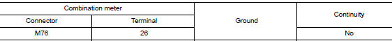
- Check continuity between combination meter harness connector M76 terminal 26 and ground.
Is the inspection result normal? YES >> Inspection End.
NO >> Repair or replace harness or connector.
Component Inspection
1.CHECK PARKING BRAKE SWITCH
Check continuity between parking brake switch terminal 1 and switch case ground.

Is the inspection result normal? YES >> Inspection End.
NO >> Replace parking brake switch. Refer to PB-7, "Exploded View".
 Fuel level sensor signal circuit
Component Function Check
1.COMBINATION METER INPUT SIGNAL
Select "METER/M&A" on "CONSULT".
Using "FUEL METER" of "Data Monitor", compare ...
 Ambient sensor signal circuit
Description
It detects outside air temperature and converts it into a resistance value
which is then input into the combination
meter.
Diagnosis Procedure
Regarding Wiring Diagram information, r ...
Other materials:
Power supply and ground circuit
BCM (BODY CONTROL SYSTEM) (WITH INTELLIGENT KEY SYSTEM)
BCM (BODY CONTROL SYSTEM) (WITH INTELLIGENT KEY SYSTEM) : Diagnosis
Procedure
Regarding Wiring Diagram information, refer to BCS-50, "Wiring Diagram".
1. CHECK FUSE
Check that the following fuse is not blown.
Is the fuse blown ...
Service data and specifications (SDS)
Wheel Bearing
Drive Shaft
Drive Shaft Specifications
*Always check with the Parts Department for the latest parts information.
Dynamic Damper Specifications
Boot Band Specification
...
Symptom diagnosis
AUDIO SYSTEM
Symptom Table
RELATED TO AUDIO
Symptoms
Check items
Probable malfunction location
The disk cannot be removed
Audio unit
Malfunction in audio unit.
Refer to AV-18, "On Board Diagnosis Function".
No sound comes out or the le ...
