Nissan Rogue Service Manual: Fuel level sensor signal circuit
Component Function Check
1.COMBINATION METER INPUT SIGNAL
- Select "METER/M&A" on "CONSULT".
- Using "FUEL METER" of "Data Monitor", compare the value of "Data Monitor" with fuel gauge pointer of combination meter.
Does the data monitor value approximately match the fuel gauge indication? YES >> Inspection End.
NO >> Replace combination meter. Refer to MWI-82, "Removal and Installation".
Diagnosis Procedure
1.CHECK FUEL LEVEL SENSOR UNIT AND FUEL PUMP (FUEL LEVEL SENSOR) CIRCUIT
- Turn ignition switch OFF.
- Disconnect combination meter connector and fuel level sensor unit and fuel pump (fuel level sensor) connector.
- Check continuity between combination meter harness connector and fuel level sensor unit and fuel pump (fuel level sensor) harness connector.

- Check continuity between combination meter harness connector and ground.
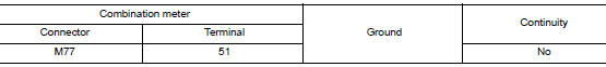
Is the inspection result normal? YES >> GO TO 2.
NO >> Repair harness or connector.
2.CHECK FUEL LEVEL SENSOR UNIT AND FUEL PUMP (FUEL LEVEL SENSOR) GROUND CIRCUIT
Check continuity between fuel level sensor unit and fuel pump (fuel level sensor) harness connector and combination meter harness connector.

Is the inspection result normal? YES >> Replace combination meter. Refer to MWI-82, "Removal and Installation".
NO >> Repair harness or connector.
Component Inspection
1.CHECK FUEL LEVEL SENSOR UNIT AND FUEL PUMP (FUEL LEVEL SENSOR)
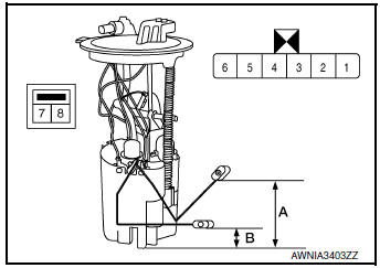
- Remove the fuel level sensor unit and fuel pump (fuel level sensor). Refer to FL-6, "Removal and Installation".
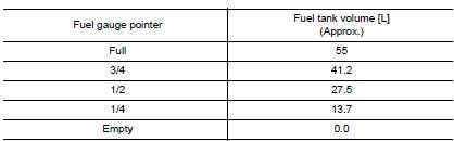
- Check the resistance between fuel level sensor unit and fuel pump (fuel level sensor).
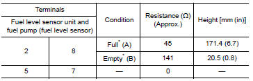
*: When float rod is contact with stopper.
Is the inspection result normal? YES >> GO TO 2.
NO >> Replace fuel level sensor unit and fuel pump (fuel level sensor). Refer to FL-6, "Removal and Installation".
2.CHECK FUEL LEVEL SENSOR UNIT (SUB)
- Remove the fuel level sensor unit (sub). Refer to FL-6, "Removal and Installation".
- Check the resistance between fuel level sensor unit (sub).


*: When float rod is contact with stopper.
Is the inspection result normal? YES >> Inspection End.
NO >> Replace fuel level sensor unit (sub). Refer to FL-6, "Removal and Installation".
 Power supply and ground circuit
COMBINATION METER
COMBINATION METER : Diagnosis Procedure
Regarding Wiring Diagram information, refer to MWI-32, "Wiring Diagram".
1.CHECK FUSES
Check that the following fuses are not bl ...
 Parking brake switch signal circuit
Description
Transmits the parking brake switch signal to the combination meter.
Component Function Check
1.COMBINATION METER INPUT SIGNAL
Start engine.
Check "PKB SW" in ...
Other materials:
Fuel injector and fuel tube
Exploded View
Rocker cover
Cylinder head
Fuel tube
Clip
O-ring (green)
Fuel injector
O-ring (black)
Front
Removal and Installation
WARNING:
Put a "CAUTION: FLAMMABLE" sign in the workshop.
Be sure to work in a well ve ...
Combination meter
Removal and Installation
REMOVAL
Disconnect the negative battery terminal. Refer to PG-77, "Removal
and Installation".
Remove the cluster lid A. Refer to IP-20, "Removal and
Installation".
Remove screws (A), from the combination meter (1).
...
Component parts
Component Parts Location
Instrument lower panel LH
No.
Component
Function
1
Combination meter
The combination meter transmittes the following signal via CAN
communications
to the TCM.
SPORT mode switch signal
...
