Nissan Rogue Service Manual: Overdrive control switch
Component Function Check
1.CHECK O/D OFF INDICATOR LAMP FUNCTION
Check O/D OFF indicator lamp turns ON for approx. 2 seconds when ignition switch turns ON.
Is the inspection results normal? YES >> GO TO 2.
NO >> Go to TM-181, "Diagnosis Procedure".
2.CHECK OVERDRIVE CONTROL SWITCH FUNCTION
- Shift the selector lever to “D” position.
- Check that O/D OFF indicator lamp turns ON/OFF when overdrive control switch is operated.
Is the inspection results normal? YES >> INSPECTION END
NO >> Go to TM-178, "Diagnosis Procedure".
Diagnosis Procedure
1.CHECK OVERDRIVE CONTROL SWITCH CIRCUIT
- Turn ignition switch OFF.
- Disconnect CVT shift selector connector.
- Turn ignition switch ON.
- Check voltage between CVT shift selector harness connector terminals.

Is the inspection result normal? YES >> GO TO 2.
NO >> GO TO 4.
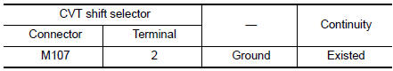
2.CHECK CVT SHIFT SELECTOR CIRCUIT
Check continuity between CVT shift selector harness connector terminals.

Is the inspection result normal? YES >> GO TO 7.
NO >> GO TO 3.
3.CHECK OVERDRIVE CONTROL SWITCH
Check overdrive control switch. Refer to TM-179, "Component Inspection".
Is the inspection result normal? YES >> Repair CVT shift selector assembly. Refer to TM-194, "Removal and Installation".
NO >> Replace selector lever knob. Refer to TM-194, "Removal and Installation".
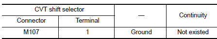
4.CHECK GROUND CIRCUIT
Check continuity between CVT shift selector harness connector terminal and ground.
Is the inspection result normal? YES >> GO TO 5.
NO >> Repair or replace malfunctioning parts.
5.CHECK CIRCUIT BETWEEN CVT SHIFT SELECTOR AND COMBINATION METER (PART 1)
- Turn ignition switch OFF.
- Disconnect combination meter connector.
- Check continuity between CVT shift selector harness connector terminal and combination meter harness connector terminal.

the inspection result normal? YES >> GO TO 6.
NO >> Repair or replace malfunctioning parts.
6.CHECK CIRCUIT BETWEEN CVT SHIFT SELECTOR AND COMBINATION METER (PART 2)
Check continuity between CVT shift selector harness connector terminal and ground.
Is the inspection result normal? YES >> GO TO 7.
NO >> Repair or replace malfunctioning parts.
7.CHECK COMBINATION METER INPUT/OUTPUT SIGNAL
- Connect all of disconnected connectors.
- Turn ignition switch ON.
- Select “Data Monitor” in “METER/M&A”.
- Select “O/D OFF SW”.
- Check that “O/D OFF SW” turns ON/OFF when overdrive control switch is operated. Refer to MWI-24, "Reference Value".
Is the inspection result normal?
YES >> Check intermittent incident. Refer to GI-41, "Intermittent Incident".
NO >> Replace combination meter. Refer to MWI-82, "Removal and Installation".
Component Inspection
1.CHECK OVERDRIVE CONTROL SW
Check continuity between wires of shift selector knob 1.
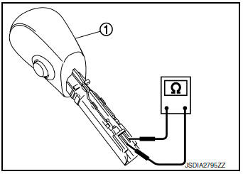

Is the inspection result normal? YES >> INSPECTION END
NO >> Replace shift selector knob. Refer to TM-194, "Removal and Installation".
 Main power supply and ground circuit
Diagnosis Procedure
1.CHECK TCM POWER CIRCUIT (PART 1)
Turn ignition switch OFF.
Disconnect TCM connector.
Check voltage between TCM harness connector terminals and ground.
...
 O/D off indicator lamp
Component Function Check
1.CHECK O/D OFF INDICATOR LAMP FUNCTION
Check O/D OFF indicator lamp turns ON for approx. 2 seconds when ignition
switch turns ON.
Is the inspection results normal?
YE ...
Other materials:
P0506 ISC system
Description
The ECM controls the engine idle speed to a specified level through the fine
adjustment of the air, which is let
into the intake manifold, by operating the electric throttle control actuator.
The operating of the throttle valve is
varied to allow for optimum control of the engine ...
CAN system (type 6)
MAIN LINE BETWEEN IPDM-E AND DLC CIRCUIT
Diagnosis Procedure
1.CHECK CONNECTOR
Turn the ignition switch OFF.
Disconnect the battery cable from the negative terminal.
Check the following terminals and connectors for damage, bend and
loose connection (connector side
an ...
Moonroof switch
Description
Transmits switch operation signal to moonroof motor and sunshade motor
assembly.
Diagnosis Procedure
Regarding Wiring Diagram information, refer to RF-17, "Wiring Diagram".
1.CHECK MOONROOF SWITCH INPUT SIGNAL
Turn ignition switch ON.
Check voltage betwe ...
