Nissan Rogue Service Manual: Main power supply and ground circuit
Diagnosis Procedure
1.CHECK TCM POWER CIRCUIT (PART 1)
- Turn ignition switch OFF.
- Disconnect TCM connector.
- Check voltage between TCM harness connector terminals and ground.
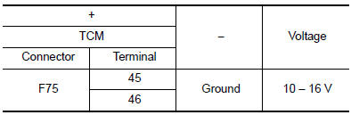
Is the inspection result normal? YES >> GO TO 2.
NO >> GO TO 4.
2.CHECK TCM POWER CIRCUIT (PART 2)
Check voltage between TCM harness connector terminals and ground.

Is the inspection result normal? YES >> GO TO 3.
NO >> GO TO 5.
3.CHECK TCM GROUND CIRCUIT
Check continuity between TCM harness connector terminals and ground.

Is the inspection result normal? YES >> Check intermittent incident. Refer to GI-41, "Intermittent Incident".
NO >> Repair or replace malfunctioning parts.
4.DETECT MALFUNCTION ITEMS (PART 1)
Check the following items:
- Open circuit or short circuit in harness between battery positive terminal and TCM connector terminal 45, and 46.
- 10A fuse (No.59, located in the fuse and fusible link block). Refer to PG-65, "Terminal Arrangement".
Is the inspection result normal? YES >> Check intermittent incident. Refer to GI-41, "Intermittent Incident".
NO >> Repair or replace malfunctioning parts.
5.CHECK CIRCUIT BETWEEN IPDM E/R AND TCM
- Turn ignition switch OFF.
- Disconnect IPDM E/R connector.
- Check continuity between IPDM E/R harness connector terminal and TCM harness connector terminals.

Is the check result normal? YES >> GO TO 6.
NO >> Repair or replace malfunctioning parts.
6.DETECT MALFUNCTIONING ITEMS (PART 2)
Check the following items:
- Open circuit or short circuit in harness between ignition switch and IPDM E/R. Refer to PG-15, "Wiring Diagram — Ignition Power Supply —".
- Short circuit in harness between IPDM E/R harness connector terminal 70 and TCM harness connector terminals 47, and 48.
- 10A fuse (No.46, located in the IPDM E/R). Refer to PG-68, "IPDM E/R Terminal Arrangement".
- IPDM E/R
Is the check result normal? YES >> Check intermittent incident. Refer to GI-41, "Intermittent Incident".
NO >> Repair or replace malfunctioning parts.
 P2815 select solenoid
DTC Description
DTC DETECTION LOGIC
DTC
CONSULT screen terms
(Trouble diagnosis content)
DTC detection condition
P2815
SELECT SOLENOID
(Select solenoid)
When all of ...
 Overdrive control switch
Component Function Check
1.CHECK O/D OFF INDICATOR LAMP FUNCTION
Check O/D OFF indicator lamp turns ON for approx. 2 seconds when ignition
switch turns ON.
Is the inspection results normal?
YE ...
Other materials:
Component parts
Component Parts Location
Steering column assembly
No.
Component
Function
1
ABS actuator and electric unit (control unit)
Transmits the following signal to EPS control unit via CAN
communication.
Vehicle speed signal (ABS)
...
Throttle valve closed position learning
Description
Throttle Valve Closed Position Learning is a function of ECM to learn the
fully closed position of the throttle
valve by monitoring the throttle position sensor output signal. It must be
performed each time the harness connector
of the electric throttle control actuator or ECM is ...
Wiring diagram
HEADLAMP
Wiring Diagram
DAYTIME LIGHT SYSTEM
Wiring Diagram
AUTO LIGHT SYSTEM
Wiring Diagram
FRONT FOG LAMP SYSTEM
Wiring Diagram
TURN SIGNAL AND HAZARD WARNING LAMP SYSTEM
Wiring Diagr ...
