Nissan Rogue Service Manual: Electrical load signal
Description
The electrical load signal (Headlamp switch signal, rear window defogger switch signal, etc.) is transferred via the CAN communication.
Component Function Check
1.CHECK REAR WINDOW DEFOGGER SWITCH FUNCTION
- Turn ignition switch ON.
- Connect CONSULT and select ÔÇťDATA MONITORÔÇŁ mode.
- Select ÔÇťLOAD SIGNALÔÇŁ and check indication under the following conditions.
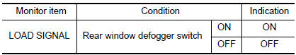
Is the inspection result normal? YES >> GO TO 2.
NO >> Proceed to EC-462, "Diagnosis Procedure".
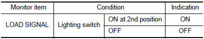
2.CHECK LIGHTING SWITCH FUNCTION
Check ÔÇťLOAD SIGNALÔÇŁ indication under the following conditions.
Is the inspection result normal? YES >> GO TO 3.
NO >> Proceed to EC-462, "Diagnosis Procedure".
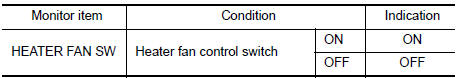
3.CHECK HEATER FAN CONTROL SWITCH FUNCTION
Select ÔÇťHEATER FAN SWÔÇŁ and check indication under the following conditions.
Is the inspection result normal? YES >> INSPECTION END
NO >> Proceed to EC-462, "Diagnosis Procedure".
Diagnosis Procedure
1.INSPECTION START
Confirm the malfunctioning circuit (rear window defogger, headlamp or heater fan). Refer to EC-462, "Component Function Check".
Which circuit is related to the incident? Rear window defogger>>GO TO 2.
Headlamp>>GO TO 3.
Heater fan>>GO TO 4.
2.CHECK REAR WINDOW DEFOGGER SYSTEM
Check rear window defogger system. Refer to DEF-19, "Work Flow".
>> INSPECTION END
3.CHECK HEADLAMP SYSTEM
Check headlamp system. Refer to EXL-82, "Work Flow" (with halogen headlamp) or EXL-219, "Work Flow" (with LED headlamp).
>> INSPECTION END
4.CHECK HEATER FAN CONTROL SYSTEM
Check heater fan control system. Refer to HAC-46, "Work Flow" (with automatic air conditioner) or HAC-146, "Work Flow" (with manual air conditioner).
>> INSPECTION END
 Cooling fan
Component Function Check
1.CHECK COOLING FAN FUNCTION
With CONSULT
Turn ignition switch ON.
Perform ÔÇťCOOLING FAN (DUAL)ÔÇŁ in ÔÇťACTIVE TESTÔÇŁ mode of ÔÇťIPDM E/RÔÇŁ
using CO ...
 Fuel injector
Component Function Check
1.INSPECTION START
Turn ignition switch to START.
Are any cylinders ignited?
YES >> GO TO 2.
NO >> Proceed to EC-464, "Diagnosis Procedure".
2. ...
Other materials:
Diagnosis and repair work flow
Work Flow
DETAILED FLOW
1.INTERVIEW FROM THE CUSTOMER
Clarify customer complaints before inspection. First of all, perform an
interview utilizing BRC-67, "Diagnostic
Work Sheet" and reproduce the symptom as well as fully understand it. Ask
customer about his/her complaints
careful ...
System description
COMPONENT PARTS
Component Parts Location
No.
Component
Description
1
Push-button ignition
switch1
Push-button ignition switch (push switch) is pressed (ON), and
transmits status signal to BCM
and IPDM E/R.
Ignition switch2
Ignition ...
Filament
Inspection and Repair
INSPECTION
When measuring voltage, wrap tin foil around the top of the
negative
probe. Then press the foil against the wire with your finger.
Attach probe circuit tester (in Volt range) to middle portion of
each filament.
If a filament is b ...
