Nissan Rogue Service Manual: Vacuum lines
Exploded View
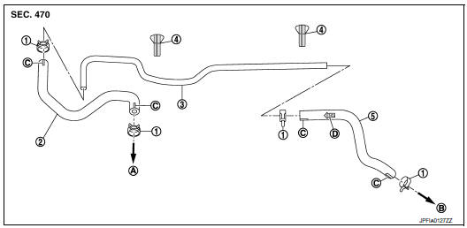
- Clamp
- Vacuum hose
- Vacuum tube
- Clip
- Vacuum hose
- To intake manifold
- To brake booster
- Paint mark
- Stamp indicating engine direction
Removal and Installation
REMOVAL
- Remove the cowl top. Refer to EXT-25, "Removal and Installation".
- Remove the air duct assembly to the electric throttle control actuator. Refer to EM-24, "Exploded View".
- Disconnect the vacuum hose from the engine intake manifold.
- Disconnect the vacuum hose from the brake booster.
- Disconnect the vacuum hose from the clip.
- Remove the vacuum hoses.
INSPECTION AFTER REMOVAL
Visual Inspection
Check for correct installation, damage and deterioration of the vacuum hoses and pipe.
INSTALLATION
Installation is in the reverse order of removal.
CAUTION:
- Insert the vacuum pipe into the vacuum hose at least 24 mm (0.94 in) as shown.
- Do not use lubricating oil during installation.
 Brake booster
Exploded View
Spacer
Gasket
Brake booster
Check valve
Reservoir tank
Brake fluid level sensor
Brake booster pressure sensor
Removal and installation
REMOVAL
...
 Front disc brake
BRAKE PAD (1 PISTON TYPE)
BRAKE PAD (1 PISTON TYPE) : Exploded View
Torque member
Bushing
Piston boot
Slide pin boot
Slide pin
Piston
Piston seal
Brake caliper ...
Other materials:
Remote keyless entry system (if so equipped)
WARNING
Radio waves could adversely affect
electric medical equipment. Those who
use a pacemaker should contact the
electric medical equipment manufacturer
for the possible influences before
use.
The remote keyless entry keyfob transmits
radio waves ...
Fuel injector and fuel tube
Exploded View
Rocker cover
Cylinder head
Fuel tube
Clip
O-ring (green)
Fuel injector
O-ring (black)
Front
Removal and Installation
WARNING:
Put a "CAUTION: FLAMMABLE" sign in the workshop.
Be sure to work in a well ve ...
Wiring diagram
NAVIGATION WITHOUT BOSE
Wiring Diagram
...
