Nissan Rogue Service Manual: Removal and installation
A/C SWITCH ASSEMBLY
Removal and Installation
REMOVAL
- Release the A/C switch assembly clips and pawls using a suitable tool.
 : Metal clip
 : Pawl
- Disconnect the harness connector from the A/C switch assembly (1) and remove.

INSTALLATION
Installation is in the reverse order of removal.
A/C AUTO AMP.
Removal and Installation
REMOVAL
- Remove heating and cooling unit assembly. Refer to HA-42, "HEATING AND COOLING UNIT ASSEMBLY : Removal and Installation".
- Disconnect the harness connectors from the A/C auto amp.
- Release pawls and remove A/C auto amp.
INSTALLATION
Installation is in the reverse order of removal.
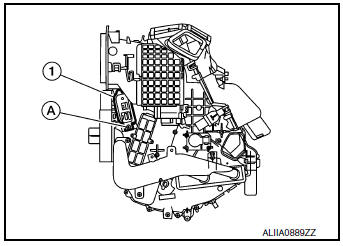
AMBIENT SENSOR
Removal and Installation
REMOVAL
- Disconnect the harness connector (A) from the ambient sensor (1).
- Release the clip and remove ambient sensor.
 : Clip
INSTALLATION
Installation is in the reverse order of removal.
IN-VEHICLE SENSOR
Removal and Installation
REMOVAL
- Remove cluster lid C. Refer to IP-21, "Removal and Installation".
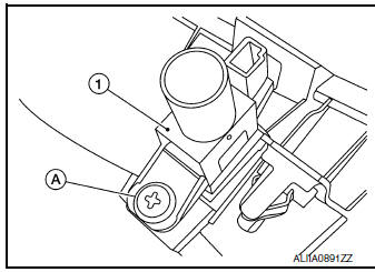
- Remove screw (A) and in-vehicle sensor (1).
INSTALLATION
Installation is in the reverse order of removal
SUNLOAD SENSOR
Removal and Installation
REMOVAL
- Release the sunload sensor pawls using a suitable tool.
- Disconnect the harness connector from the sunload sensor (1) and remove.

INSTALLATION
Installation is in the reverse order of removal.
INTAKE SENSOR
Exploded View

- Intake sensor
- Heating and cooling unit assembly
Removal and Installation
REMOVAL
- Remove front foot duct (LH). Refer to VTL-10, "FRONT FOOT DUCT : Removal and Installation".
- Disconnect the harness connector and remove intake sensor
INSTALLATION
Installation is in the reverse order of removal.
REFRIGERANT PRESSURE SENSOR
Removal and Installation
REMOVAL
- Discharge the refrigerant. Refer to HA-23, "Recycle Refrigerant".
- Remove front bumper fascia. Refer to EXT-17, "Removal and Installation".
- Disconnect the harness connector from the refrigerant pressure sensor.
- Remove the refrigerant pressure sensor (1) from the condenser.
 : Front
CAUTION: Cap or wrap the opening of the refrigerant pressure sensor with suitable material such as vinyl tape to avoid the entry of air.

INSTALLATION
Installation is in the reverse order of removal.
CAUTION:
- Do not reuse O-ring.
- Apply A/C oil to new O-ring for installation.
- After charging refrigerant, check for leaks. Refer to HA-21, "Leak Test".
DOOR MOTOR
Component Parts Location
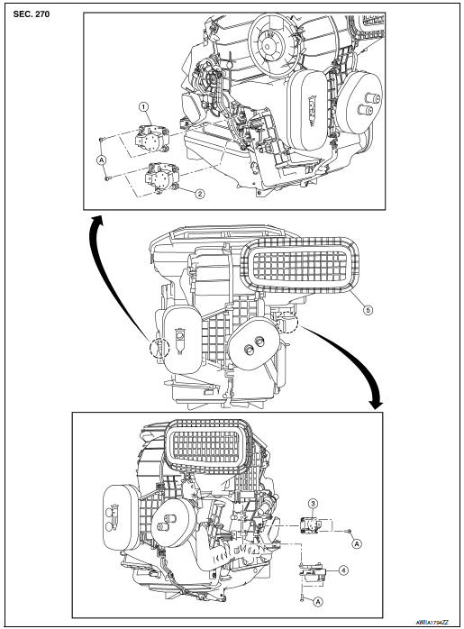
- Mode door motor
- Air mix door motor (RH)
- Air mix door motor (LH)
- Intake door motor
- Heating and cooling unit assembly
- Screw
INTAKE DOOR MOTOR
INTAKE DOOR MOTOR : Removal and Installation
REMOVAL
- Remove front foot duct (LH). Refer to VTL-10, "FRONT FOOT DUCT : Removal and Installation".
- Disconnect the harness connector from the intake door motor.
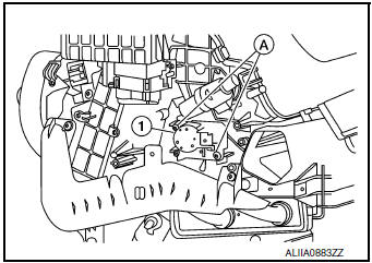
- Remove screws (A) and intake door motor (1).

INSTALLATION
Installation is in the reverse order of removal.
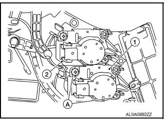
MODE DOOR MOTOR
MODE DOOR MOTOR : Removal and Installation
REMOVAL
- Remove front foot duct (RH). Refer to VTL-10, "FRONT FOOT DUCT : Removal and Installation".
- Disconnect the harness connector from the mode door motor.
- Remove screws (A) and mode door motor (1).
(2): Air mix doot motor (RH)

INSTALLATION
Installation is in the reverse order of removal.
AIR MIX DOOR MOTOR
AIR MIX DOOR MOTOR : Removal and Installation
REMOVAL
Air Mix Door Motor (LH)
- Remove front foot duct (LH). Refer to VTL-10, "FRONT FOOT DUCT : Removal and Installation".
- Disconnect the harness connector from the air mix door motor (LH).
- Remove screws (A) and air mix door motor (LH) (1).
Air Mix Door Motor (RH)
- Remove front foot duct (RH). Refer to VTL-10, "FRONT FOOT DUCT : Removal and Installation".
- Disconnect the harness connector from the air mix door motor (RH).
- Remove screws (A) and air mix door motor (RH) (1).
(2): Mode door motor
INSTALLATION
Installation is in the reverse order of removal.
VARIABLE BLOWER CONTROL
Removal and Installation
REMOVAL
- Remove center console side finisher (LH). Refer to IP-18, "Exploded View".
- Disconnect the harness connector from the variable blower control.
- Remove screw (A) and variable blower control (1).
INSTALLATION
Installation is in the reverse order of removal.
 Symptom diagnosis
HEATER AND AIR CONDITIONING SYSTEM CONTROL SYMPTOMS
Diagnosis Chart By Symptom
NOTE:
Perform the self-diagnoses with CONSULT before performing the symptom diagnosis.
If DTC is detected, perform
...

Other materials:
Manual operation
Fan speed control
Press the fan control buttons
to manually
control the fan speed.
Press the AUTO button to return to automatic
control of the fan speed.
Air recirculation
Press the air recirculation
button to recirculate
interior air inside the vehicle. The
indicator light on the ...
Unit removal and installation
FRONT SUSPENSION MEMBER
Exploded View
Front suspension member
Strut mounting bearing
Rebound stopper insulator
Rebound stopper
Removal and Installation
REMOVAL
Remove the wheel and tire using power tool. Refer to WT-60,
"Removal and Installation&quo ...
C1155 brake fluid level switch
DTC Logic
DTC DETECTION LOGIC
DTC
Display Item
Malfunction detected condition
Possible causes
C1155
BR FLUID LEVEL LOW
When brake fluid level low signal is detected
Harness or connector
ABS actuator and electric unit
(control unit)
...
