Nissan Rogue Service Manual: P1805 brake switch
DTC Description
DTC DETECTION LOGIC
| DTC No. | CONSULT screen terms (Trouble diagnosis content) | DTC detecting condition |
| P1805 | BRAKE SW/CIRCUIT (BRAKE SW/CIRCUT) | A stop lamp switch signal is not sent to ECM for extremely long time while the vehicle is driving. |
POSSIBLE CAUSE
- Harness or connectors (Stop lamp switch circuit is open or shorted.)
- Stop lamp switch
FAIL-SAFE ECM controls the electric throttle control actuator by regulating the throttle opening to a small range. Therefore, acceleration will be poor.
| Vehicle condition | Driving condition |
| When engine is idling | Normal |
| When accelerating | Poor acceleration |
DTC CONFIRMATION PROCEDURE
1.PERFORM DTC CONFIRMATION PROCEDURE
- Turn ignition switch ON.
- Fully depress the brake pedal for at least 5 seconds.
- Erase the DTC.
- Check 1st trip DTC.
Is 1st trip DTC detected? YES >> Proceed to EC-418, "Diagnosis Procedure".
NO >> INSPECTION END
Diagnosis Procedure
1.CHECK STOP LAMP SWITCH POWER SUPPLY CIRCUIT
- Turn ignition switch OFF.
- Disconnect stop lamp switch harness connector.
- Check the voltage between stop lamp switch harness connector and ground.

Is the inspection result normal? YES >> GO TO 2.
NO >> Perform the trouble diagnosis for power supply circuit.
2.CHECK STOP LAMP SWITCH GROUND CIRCUIT
- Disconnect ECM harness connector.
- Check the continuity between stop lamp switch harness connector and ECM harness connector
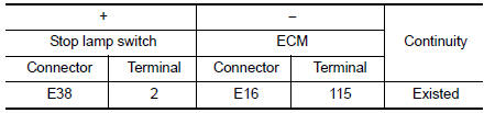
- Also check harness for short to ground and to power.
Is the inspection result normal? YES >> GO TO 3.
NO >> Repair or replace error-detected parts.
3.CHECK STOP LAMP SWITCH
Check the stop lamp switch. Refer to EC-412, "Component Inspection (Stop Lamp Switch)".
Is the inspection result normal? YES >> Check intermittent incident. Refer to GI-41, "Intermittent Incident".
NO >> Replace stop lamp switch. Refer to BR-20, "Exploded View".
Component Inspection (Stop Lamp Switch)
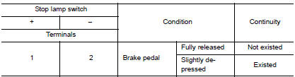
1.CHECK STOP LAMP SWITCH-1
- Turn ignition switch OFF.
- Disconnect stop lamp switch harness connector.
- Check the continuity between stop lamp switch terminals as per the following conditions.

Is the inspection result normal? YES >> INSPECTION END
NO >> GO TO 2.
2.CHECK STOP LAMP SWITCH-2
- Adjust stop lamp switch installation. Refer to BR-15, "Adjustment".
- Check the continuity between stop lamp switch terminals as per the following conditions.
Is the inspection result normal? YES >> INSPECTION END
NO >> Replace stop lamp switch. Refer to BR-20, "Exploded View".
 P1715 input speed sensor
Description
ECM receives input speed sensor signal from TCM through CAN communication
line. ECM uses this signal for
engine control.
DTC Description
DTC DETECTION LOGIC
DTC No.
CONSUL ...
 P2004 intake manifold runner control valve
DTC Description
DTC DETECTION LOGIC
DTC No.
CONSULT screen terms
(Trouble diagnosis content)
DTC detecting condition
P2004
TUMBLE CONT/V
(Intake manifold runner contro ...
Other materials:
Oil
Description
MAINTENANCE OF OIL LEVEL
The compressor oil is circulating in the system together with the
refrigerant. It is necessary to fill compressor
with oil when replacing A/C system parts or when a large amount of refrigerant
leak is detected. It is important
to always maintain oil level ...
Diagnosis system (combination meter)
Description
COMBINATION METER SELF-DIAGNOSIS MODE
The following meter functions can be checked during Combination Meter
Self-Diagnosis Mode:
Pointer sweep of speedometer, tachometer and gauges.
Illumination of all LCD segments and color patterns for meter
displays.
I ...
Off-road recovery
If the right side or left side wheels unintentionally
leave the road surface, maintain control of the
vehicle by following the procedure below. Please
note that this procedure is only a general guide.
The vehicle must be driven as appropriate based
on the conditions of the vehicle, road and t ...