Nissan Rogue Service Manual: P0112, P0113 IAT sensor
DTC Description
DTC DETECTION LOGIC
| DTC No. | CONSULT screen terms (Trouble diagnosis content) | DTC detecting condition |
| P0112 | IAT SEN/CIRCUIT- B1 (Intake air temperature sensor 1 circuit low bank 1) | An excessively low voltage from the intake air temperature sensor is sent to ECM. |
| P0113 | IAT SEN/CIRCUIT- B1 (Intake air temperature sensor 1 circuit high bank 1) | An excessively high voltage from the intake air temperature sensor is sent to ECM. |
POSSIBLE CAUSE
- Harness or connectors (Intake air temperature sensor circuit is open or shorted.)
- Intake air temperature sensor
- Sensor power supply 2 circuit
FAIL-SAFE
Not applicable
DTC CONFIRMATION PROCEDURE
1.PRECONDITIONING
If DTC Confirmation Procedure has been previously conducted, always perform the following procedure before conducting the next test.
- Turn ignition switch OFF and wait at least 10 seconds.
- Turn ignition switch ON.
- Turn ignition switch OFF and wait at least 10 seconds.
>> GO TO 2.
2.PERFORM DTC CONFIRMATION PROCEDURE
- Turn ignition switch ON and wait at least 5 seconds.
- Check 1st trip DTC.
Is 1st trip DTC detected? YES >> Proceed to EC-208, "Diagnosis Procedure".
NO >> INSPECTION END
Diagnosis Procedure
1.CHECK INTAKE AIR TEMPERATURE SENSOR POWER SUPPLY
- Turn ignition switch OFF.
- Disconnect mass air flow sensor (with intake air temperature sensor) harness connector.
- Turn ignition switch ON.
- Check the voltage between mass air flow sensor harness connector and ground.

Is the inspection result normal? YES >> GO TO 3.
NO >> GO TO 2.
2.CHECK INTAKE AIR TEMPERATURE SENSOR POWER SUPPLY CIRCUIT
- Turn ignition switch OFF.
- Disconnect ECM harness connector.
- Check the continuity between mass air flow sensor harness connector and ECM harness connector.

- Also check harness for short to ground.
Is the inspection result normal? YES >> Perform the trouble diagnosis for power supply circuit.
NO >> Repair or replace error-detected parts.
3.CHECK INTAKE AIR TEMPERATURE SENSOR GROUND CIRCUIT
- Turn ignition switch OFF.
- Disconnect ECM harness connector.
- Check the continuity between mass air flow sensor harness connector and ECM harness connector.
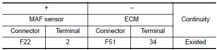
- Also check harness for short to power.
Is the inspection result normal? YES >> GO TO 4.
NO >> Repair or replace error-detected parts.
4.CHECK INTAKE AIR TEMPERATURE SENSOR
Check the intake air temperature sensor. Refer to EC-207, "Component Inspection".
Is the inspection result normal? YES >> GO TO 5.
NO >> Replace mass air flow sensor (with intake air temperature sensor). Refer to EM-24, "Exploded View".
5.CHECK INTERMITTENT INCIDENT
Refer to GI-41, "Intermittent Incident".
>> INSPECTION END
Component Inspection
1.CHECK INTAKE AIR TEMPERATURE SENSOR
- Turn ignition switch OFF.
- Disconnect mass air flow sensor harness connector and reconnect it again.
- Turn ignition switch ON.
- Select “DATA MONITOR” mode with CONSULT.
- Check that “INT/A TEMP SEN” indicates as per following condition.
| Monitor item | Condition | Value (Approx.) |
| INT/A TEMP SEN | Temperature [°C (°F)] 25 (77) | 1.9 - 2.1 (V) |
Is the inspection result normal?
YES >> INSPECTION END
NO >> Replace mass air flow sensor (with intake air temperature sensor). Refer to EM-24, "Exploded View".
 P0111 IAT sensor
DTC Description
DTC DETECTION LOGIC
DTC No.
CONSULT screen terms
(Trouble diagnosis content)
DTC detecting condition
P0111
IAT SENSOR 1 B1
(Intake air temperature sens ...
 P0116 ECT sensor
DTC Description
DTC DETECTION LOGIC
DTC No.
CONSULT screen terms
(Trouble diagnosis content)
DTC detecting condition
P0116
ECT SENSOR
(Engine coolant temperature senso ...
Other materials:
Removal and installation
BCM (BODY CONTROL MODULE)
Removal and Installation
CAUTION:
Before replacing the BCM, perform “READ CONFIGURATION” to save or print current
vehicle specification.
Refer to BCS-120, "ADDITIONAL SERVICE WHEN REPLACING CONTROL UNIT (BCM) : Work
Procedure".
REMOVAL
Disc ...
Moonroof switch
Removal and Installation
REMOVAL
Remove map lamp assembly. Refer to INL-55, "Removal and Installation".
Using a suitable tool release clip from harness connector.
: Clip
Using a suitable tool release pawls and remove moonroof switch
finisher (1).
Using a ...
Rear RH side power window does not operate
WITH BOTH POWER WINDOW MAIN SWITCH AND REAR POWER WINDOW
SWITCH RH
WITH BOTH POWER WINDOW MAIN SWITCH AND REAR POWER WINDOW
SWITCH RH : Diagnosis Procedure
1.CHECK REAR POWER WINDOW SWITCH
Check rear power window switch.
Refer to PWC-36, "Component Function Check".
Is the inspec ...
