Nissan Rogue Service Manual: Key switch signal circuit (without intelligent key)
Description
Transmits a key switch signal to the BCM.
Component Function Check
1. CHECK BCM INPUT SIGNAL
Select "Data Monitor" for "BCM" and check the "KEY ON SW" monitor value.

Is the inspection result normal? YES >> Inspection End.
NO >> Refer to WCS-47, "Diagnosis Procedure".
Diagnosis Procedure
Regarding Wiring Diagram information, refer to WCS-29, "Wiring Diagram".
1. CHECK BCM INPUT SIGNAL
Check voltage between BCM harness connector M19 terminal 81 and ground.

Is the inspection result normal? YES >> Inspection End.
NO >> GO TO 2.
2. CHECK KEY SWITCH CIRCUIT
- Disconnect BCM connector M19 and key switch.
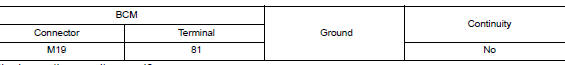
- Check continuity between BCM harness connector M19 terminal 81 and key switch harness connector M105 terminal 1.

- Check continuity between BCM harness connector M19 terminal 81 and ground.
Is the inspection result normal? YES >> GO TO 3.
NO >> Repair or replace harness or connector.
3. CHECK KEY SWITCH POWER SUPPLY CIRCUIT
Check voltage between key switch harness connector M105 terminal 1 and ground.

Is the inspection result normal? YES >> GO TO 4.
NO >> Repair or replace harness or connector.
4. CHECK KEY SWITCH GROUND CIRCUIT
Check continuity between key switch harness connector M105 terminal 2 and ground.

Is the inspection result normal? YES >> Replace key switch.
NO >> Repair or replace harness or connector.
Component Inspection
1. CHECK KEY SWITCH
- Turn ignition switch OFF.
- Disconnect key switch.
- Check continuity between key switch terminals 1 and 2.

Is the inspection result normal? YES >> Inspection End.
NO >> Replace key switch.
 Parking brake switch signal circuit
Component Function Check
1.CHECK PARKING BRAKE SWITCH OPERATION
Check that brake warning lamp in combination meter turns ON/OFF when parking
brake is actuated.
Is the inspection result normal?
...

Other materials:
Intermittent incident
DESCRIPTION
Sometimes the symptom is not present when the vehicle is brought in for
service. If possible, re-create the
conditions present at the time of the incident. Doing so may help avoid a No
Trouble Found Diagnosis. The following section illustrates ways to simulate the
conditions/envi ...
Brake warning lamp
Component Function Check
1.CHECK BRAKE WARNING LAMP FUNCTION
Check that brake warning lamp in combination meter turns ON for 1 second
after ignition switch is turned ON.
CAUTION:
Never start the engine.
Is the inspection result normal?
YES >> GO TO 2.
NO >> Proceed to BRC-12 ...
CAN system (type 2)
MAIN LINE BETWEEN IPDM-E AND DLC CIRCUIT
Diagnosis Procedure
1.CHECK CONNECTOR
Turn the ignition switch OFF.
Disconnect the battery cable from the negative terminal.
Check the following terminals and connectors for damage, bend and
loose connection (connector side
an ...
