Nissan Rogue Service Manual: ECU diagnosis information
BCM
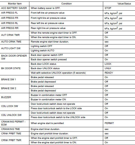
Reference Value
NOTE: The Signal Tech II Tool (J-50190) can be used to perform the following functions. Refer to the Signal Tech II User Guide for additional information.
- Activate and display TPMS sensor IDs
- Display tire pressure reported by the TPMS sensor
- Read TPMS DTCs
- Register TPMS sensor IDs
- Check Intelligent Key relative signal strength
- Confirm vehicle Intelligent Key antenna signal strength
VALUES ON THE DIAGNOSIS TOOL


TERMINAL LAYOUT

PHYSICAL VALUES


Fail Safe

DTC Inspection Priority Chart
If some DTCs are displayed at the same time, perform inspections one by one based on the following priority chart.


DTC Index
NOTE: Details of time display
- CRNT: Displays when there is a malfunction now or after returning to the normal condition until turning ignition switch OFF → ON again.
- 1 - 39: Displayed if any previous malfunction is present when current condition is normal. It increases like 1 → 2 → 3...38 → 39 after returning to the normal condition whenever ignition switch OFF → ON. The counter remains at 39 even if the number of cycles exceeds it. It is counted from 1 again when turning ignition switch OFF → ON after returning to the normal condition if the malfunction is detected again.


 System description
COMPONENT PARTS
BODY CONTROL SYSTEM
BODY CONTROL SYSTEM : Component Parts Location
BCM
Behind instrument panel (LH)
POWER CONSUMPTION CONTROL SYSTEM
POWER CONSUMPTION CONTROL SYS ...
 Wiring diagram
BCM
Wiring Diagram
...
Other materials:
P0717 input speed sensor A
DTC Description
DTC DETECTION LOGIC
DTC
CONSULT screen terms
(Trouble diagnosis content)
DTC detection condition
P0717
INPUT SPEED SENSOR A
(Input/Turbine Speed Sensor “A” Circuit No
Signal)
When 1 is satisfied and any of 2, 3 or 4 is satisfied:
W ...
System description
COMPONENT PARTS
Component Parts Location
View right of steering column.
No.
Component
Function
1
Combination meter
Combination meter transmits the vehicle speed signal to BCM via CAN
communication.
BCM also receives the vehicle speed signal f ...
P0643 sensor power supply
Description
ECM supplies a voltage of 5 V to some of the sensors systematically divided
into 2 groups, respectively.
Accordingly, when a short circuit develops in a sensor power source, a
malfunction may occur simultaneously
in the sensors belonging to the same group as the short-circuited ...
