Nissan Rogue Service Manual: Cooling fan
Exploded View
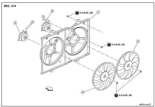
- Fan shroud
- Fan motor (LH)
- Fan motor (RH)
- Cooling fan (RH)
- Cooling fan (LH)
 Front
Front
Removal and Installation
REMOVAL
WARNING: Do not remove the radiator cap when the engine is hot. Serious burns could occur from high pressure engine coolant escaping from the radiator. Wrap a thick cloth around the cap. Slowly turn it a quarter turn to allow built-up pressure to escape. Carefully remove the cap by turning it all the way.
NOTE: When removing components such as hoses, tubes/lines, etc., cap or plug openings to prevent fluid from spilling.
- Disconnect battery negative terminal.
- Disconnect battery positive terminal. Refer to PG-77, "Exploded View".
- Depower SRS system. Refer to SR-2, "Service".
- Drain engine coolant from radiator. Refer to CO-8, "Draining".
CAUTION:
- Perform this step when the engine is cold.
- Do not spill engine coolant on the drive belt.
- Remove engine under cover. Refer to EXT-37, "ENGINE UNDER COVER : Removal and Installation".
- Remove front air spoiler. Refer to EXT-16, "Exploded View".
- Remove fender protector side cover. Refer to EXT-28, "FENDER PROTECTOR : Exploded View".
- Remove air duct (inlet). Refer to EM-24, "Exploded View".
- Remove bumper fascia assembly. Refer to EXT-16, "Exploded View".
- Remove radiator core support (upper). Refer to XX.
- Remove radiator hose (upper) from radiator. Refer to CO-13, "Exploded
View".
CAUTION: Do not spill engine coolant on the drive belt.
- Disconnect harness connector from cooling fan controller.
- Remove harness retainers from fan shroud.
- Remove CVT cooler hose retainers from fan shroud.
- Remove reservoir tank hose from fan shroud. Refer to CO-13, "Exploded View".
- Remove fan shroud. Refer to CO-17, "Exploded View".
CAUTION: Be careful not to damage the radiator.
INSTALLATION
Installation is in the reverse order of removal.
CAUTION: Do not spill engine coolant in the engine compartment. Use a shop cloth to absorb engine coolant.
NOTE: Cooling fan is controlled by ECM. For details, refer to EC-64, "On Board Diagnosis Function".
Disassembly and Assembly
DISASSEMBLY
- Remove cooling fan mounting nuts, and then remove the cooling fans (RH and LH).
- Remove fan motor cover and fan motors (RH and LH).
ASSEMBLY
Assembly is in the reverse order of disassembly.
CAUTION: Apply high thread locking sealant to cooling fan motor shaft.
Inspection
INSPECTION AFTER DISASSEMBLY
Cooling Fan
Inspect cooling fan for cracks or unusual bends.
- If anything is found, replace cooling fan.
 Radiator
Exploded View
REMOVAL
Reservoir tank
Reservoir tank cap
Reservoir tank hose
Mounting rubber (upper)
Radiator cap
Radiator
CVT fluid cooler hose
...
 Water pump
Exploded View
Cylinder block
Water pump
Water pump gasket
Water pump housing
O-ring
Water pipe
Water pump housing gasket
Refer to INSTALLAT ...
Other materials:
Rear bumper
Exploded View
Rear bumper fascia side bracket
(LH)
Rear mud protector
Rear bumper reinforcement support
(LH)
Rear bumper fascia undercover
(LH)
Rear bumper reinforcement
Rear energy absorber
Rear bumper bracket (LH)
Rear bumper fascia
Rear bumper fascia re ...
System
MOONROOF
MOONROOF : System Diagram
MOONROOF & SUNSHADE
MOONROOF : System Description
MOONROOF SYSTEM
INPUT/OUTPUT SIGNAL CHART
Item
Input signal to moonroof motor assembly
Moonroof motor function
Actuator
Moonroof switch
Moonroof signal (tilt ...
NISSAN Jackknife key (if so equipped)
Replace the battery in the jackknife key as follows:
Hold jackknife key button side up. Insert a
small screwdriver into the slit of the corner
and twist it to separate the upper part from
the lower part. Use a cloth to protect the
casing.
Remove old battery.
Replace t ...
