Nissan Rogue Service Manual: Cooler pipe and hose
Exploded View

- Condenser
- High-pressure flexible hose
- Low-pressure flexible hose
- Low-pressure pipe
- Heating and cooling unit assembly
- High-pressure pipe
- Compressor
- O-ring
- Low-pressure service port
- High-pressure service port
LOW-PRESSURE PIP
LOW-PRESSURE PIPE : Removal and Installation
REMOVAL
- Discharge the refrigerant. Refer to HA-23, "Recycle Refrigerant".
- Remove bolts (A) and engine upper mount (1).

- Remove the bolt (A) that retains the low-pressure flexible hose to the low-pressure pipe.
CAUTION: Cap or wrap the joint of the pipe with suitable material such as vinyl tape to avoid the entry of air.

- Remove low-pressure pipe bracket bolts (A) and bracket.

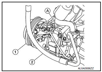
- Release high-pressure pipe (2) from clamp (A).
- Remove nut (B) and low-pressure pipe (1).

- Remove the bolt (A) that retains the low-pressure and high-pressure pipe to the expansion valve (1).
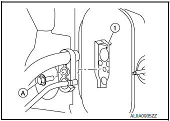
- Remove low-pressure pipe.
INSTALLATION
Installation is in the reverse order of removal.
CAUTION:
- Tighten bolts to specified torque. Refer to HA-32, "Exploded View".
- Do not reuse O-rings.
- Apply A/C oil to new O-rings for installation.
- After charging refrigerant, check for leaks. Refer to HA-21, "Leak Test".
LOW-PRESSURE FLEXIBLE HOSE
LOW-PRESSURE FLEXIBLE HOSE : Removal and Installation
REMOVAL
- Discharge the refrigerant. Refer to HA-23, "Recycle Refrigerant".
- Remove the bolt (A) that retains the low-pressure flexible hose to the low-pressure pipe.
CAUTION: Cap or wrap the joint of the pipe with suitable material such as vinyl tape to avoid the entry of air.

- Remove the nut (A) that retains the low-pressure flexible hose to the compressor.

- Remove the low-pressure flexible hose.
INSTALLATION
Installation is in the reverse order of removal.
CAUTION:
- Tighten nut/bolt to specified torque. Refer to HA-32, "Exploded View".
- Do not reuse O-rings.
- Apply A/C oil to new O-rings for installation.
- After charging refrigerant, check for leaks. Refer to HA-21, "Leak Test".
HIGH-PRESSURE PIPE
HIGH-PRESSURE PIPE : Removal and Installation
REMOVAL
- Discharge the refrigerant. Refer to HA-23, "Recycle Refrigerant".
- Remove front bumper fascia. Refer to EXT-17, "Removal and Installation".
- Remove air duct assembly. Refer to EM-24, "Exploded View".
- Remove bolts (A) and upper engine mount (1).

- Release high-pressure pipe (2) from clamp (A).
(1): Low-pressure pipe
(B): Nut

- Remove bolt (A) that retains high-pressure pipe (1) to the condenser
(2).
CAUTION: Cap or wrap the joint of the pipe with suitable material such as vinyl tape to avoid the entry of air.

- Remove the bolt (A) that retains the high-pressure and low-pressure pipe to the expansion valve (1).

- Remove high-pressure pipe.
INSTALLATION
Installation is in the reverse order of removal.
CAUTION:
- Tighten bolts to specified torque. Refer to HA-32, "Exploded View".
- Do not reuse O-rings.
- Apply A/C oil to new O-rings for installation.
- After charging the refrigerant, check for leaks. Refer to HA-21, "Leak Test".
HIGH-PRESSURE FLEXIBLE HOSE
HIGH-PRESSURE FLEXIBLE HOSE : Removal and Installation
REMOVAL
- Discharge the refrigerant. Refer to HA-23, "Recycle Refrigerant".
- Remove front bumper fascia. Refer to EXT-17, "Removal and Installation".
- Remove the bolt (A) that retains the high-pressure flexible hose (2) to the condenser (1).
CAUTION: Cap or wrap the joint of the pipe with suitable material such as vinyl tape to avoid the entry of air.

- Remove the bolt (A) that retains the high-pressure flexible hose (2) to the compressor (1).
INSTALLATION
Installation is in the reverse order of removal.
CAUTION:
- Tighten bolts to specified torque. Refer to HA-37, "Exploded View".
- Do not reuse O-rings.
- Apply A/C oil to new O-rings for installation.
- After charging the refrigerant, check for leaks. Refer to HA-21, "Leak Test".
 Compressor
Exploded View
Compressor
Removal and Installation
REMOVAL
Discharge the refrigerant. Refer to HA-23, "Recycle Refrigerant".
Remove the engine under cover. Refer to EX ...
 Condenser
Exploded View
Air guide (LH)
Condenser upper bracket (LH)
Condenser (includes liquid tank)
Condenser upper bracket (RH)
Air guide (RH)
Refrigerant pressure sensor
C ...
Other materials:
System description
COMPONENT PARTS
Component Parts Location
No.
Component
Function
1
Combination meter
Combination meter transmits the vehicle speed signal to BCM via CAN
communication.
BCM also receives the vehicle speed signal from ABS actuator and
electric
...
Settings
The setting mode allows you to change the information
displayed in the vehicle information display:
Driver Assistance
Clock
Meter Settings
Vehicle Settings
Maintenance
Alarm
Tire Pressure
Unit
Language
Factory Reset
...
Removal and installation
NATS ANTENNA AMP.
Exploded View
Instrument finisher B
Push button ignition switch
NATS antenna amp.
Pawl
Removal and Installation
REMOVAL
Remove the instrument finisher B. Refer to IP-16, "INSTRUMENT
FINISHER B : Removal and Installation".
Release ...
