Nissan Rogue Service Manual: Brake booster
Inspection
Operation
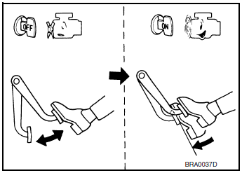
Depress the brake pedal several times at five second intervals with the engine stopped. Start the engine with the brake pedal fully depressed. Check that the clearance between brake pedal and dash lower panel decreases.
NOTE: A slight impact with a small click may be felt on the pedal when the brake pedal is fully depressed. This is normal brake system operation.

Vacuum Inspection
Idle the engine for one minute to apply vacuum to the brake booster.
Stop the engine. Depress the brake pedal several times at five second intervals until the accumulated vacuum is released to atmospheric pressure. Check that the clearance between brake pedal and dash lower panel gradually increases (A → B → C) each time the brake pedal is depressed during this operation.

Depress the brake pedal with the engine running. Then stop the engine while holding down the brake pedal. Check that the brake pedal stroke does not change after holding down the brake pedal for 30 seconds or more.
NOTE: A slight impact with a small click may be felt on the pedal when the brake pedal is fully depressed. This is normal brake system operation.

 Brake master cylinder
Inspection
Check for brake fluid leakage at the following areas:
Master cylinder mounting face
Reservoir tank mounting face
Brake tube and brake tube connections
Bra ...
 Front disc brake
BRAKE PAD
BRAKE PAD : Inspection
Check brake pad wear thickness from an inspection hole (A) on cylinder
body. Check using a scale if necessary.
Wear thickness : Refer to BR-55, "Front Dis ...
Other materials:
Vehicle Dynamic Control (VDC) system
The Vehicle Dynamic Control (VDC) system uses
various sensors to monitor driver inputs and vehicle
motion. Under certain driving conditions,
the VDC System helps to perform the following
functions:
Controls brake pressure to reduce wheel
slip on 1 slipping drive wheel so power is
t ...
Precaution
Precaution for Supplemental Restraint System (SRS) "AIR BAG" and "SEAT
BELT
PRE-TENSIONER"
The Supplemental Restraint System such as “AIR BAG” and “SEAT BELT PRE-TENSIONER”,
used along
with a front seat belt, helps to reduce the risk or severity of injury to the
...
Compressor system symptoms
Symptom Table
Follow the next table and perform trouble diagnosis if there is a compressor
unit malfunction (internal noise,
insufficient cooling).
Symptom
Inspection method
Check list
Result
Action
Noise from compressor unit
When A/C is ON.
...
