Nissan Rogue Service Manual: Steering switch
Description
When one of the steering switches is pushed, the resistance in the steering switch changes the signal to identify which button is controlling the information display.
Diagnosis Procedure
Regarding Wiring Diagram information, refer to MWI-32, "Wiring Diagram".
1.CHECK STEERING SWITCH CIRCUIT
- Turn ignition switch OFF.
- Disconnect combination meter harness connector M76 and spiral cable harness connector M30.
- Check continuity between combination meter harness connector M76 and spiral cable harness connector M30.

- Check continuity between combination meter harness connector M76 and ground.

Is the inspection result normal? YES >> Inspection End.
NO >> Repair or replace harness or connector.
Component Inspection
1.CHECK STEERING SWITCH RESISTANCE
Check resistance between the following steering switch terminals.

Is the inspection result normal? YES >> GO TO 2.
NO >> Replace steering wheel switch. Refer to AV-65, "Removal and Installation".
2.CHECK SPIRAL CABLE
Check continuity between the following spiral cable terminals.
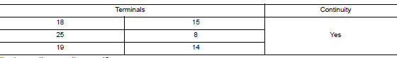
Is the inspection result normal? YES >> Inspection End.
NO >> Replace spiral cable. Refer to SR-15, "Removal and Installation".
 Meter control switch signal circuit
Diagnosis Procedure
Regarding Wiring Diagram information, refer to MWI-32, "Wiring Diagram".
1.CHECK METER CONTROL SWITCH SIGNAL
Turn ignition switch ON.
Check voltage be ...
 Washer level switch signal circuit
Description
Transmits the washer fluid level switch signal to the combination meter.
Diagnosis Procedure
Regarding Wiring Diagram information, refer to MWI-32, "Wiring Diagram".
1.CHECK ...
Other materials:
Diagnosis system (BCM)
WITH INTELLIGENT KEY
WITH INTELLIGENT KEY : CONSULT Function (BCM - COMMON ITEM)
APPLICATION ITEM
CONSULT performs the following functions via CAN communication with BCM.
Direct Diagnostic Mode
Description
Ecu Identification
The BCM part number is displayed.
Self D ...
C1142 press sensor
DTC Logic
DTC DETECTION LOGIC
DTC
Display Item
Malfunction detected condition
Possible causes
C1142
PRESS SEN CIRCUIT
When a malfunction is detected in master cylinder
pressure sensor
Stop lamp switch system
ABS actuator and electric unit
...
Passenger side door mirror defogger
Description
Heats the heating wire with the power supply from the rear window defogger
relay to prevent the door mirror
from fogging up.
Component Function Check
1.CHECK DOOR MIRROR DEFOGGER RH
Check that the heating wire of door mirror defogger RH is heated when turning
the rear window def ...
