Nissan Rogue Service Manual: Harness
Harness Layout
HOW TO READ HARNESS LAYOUT
The following Harness Layouts use a map style grid to help locate connectors on the drawings:
- Main Harness and Main Sub Harness
- Engine Room Harness
- Engine Room Harness (Passenger Compartment)
- Front End Module Harness
- Engine Control Harness
- Body Harness
- Body No. 2 Harness
- Room Lamp Harness
To use the grid reference
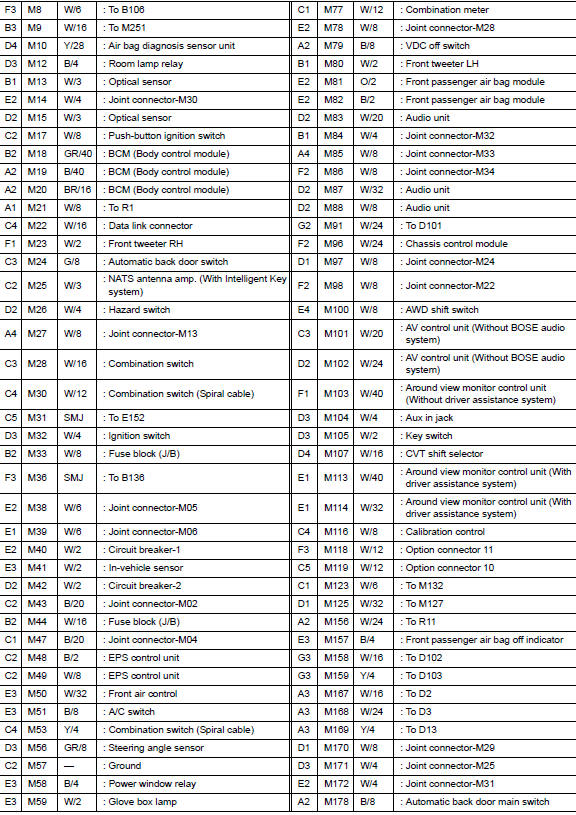
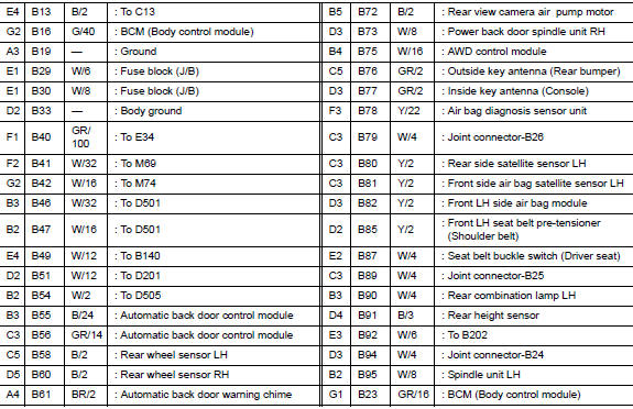
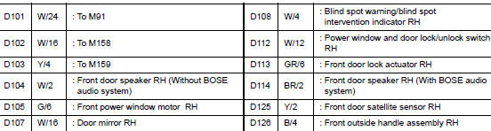
- Find the desired connector number on the connector list.
- Find the grid reference.
- On the drawing, find the crossing of the grid reference letter column and number row.
- Find the connector number in the crossing zone.
- Follow the line (if used) to the connector.

OUTLINE

MAIN HARNESS


ENGINE ROOM HARNESS


ENGINE ROOM HARNESS (PASSENGER COMPARTMENT)


FRONT END MODULE HARNESS


ENGINE CONTROL HARNESS


BODY HARNESS


BODY NO. 2 HARNESS


ROOM LAMP HARNESS


FRONT DOOR LH HARNESS


FRONT DOOR RH HARNESS

REAR DOOR LH HARNESS


REAR DOOR RH HARNESS


BACK DOOR HARNESS


 Ground
Ground Distribution
MAIN HARNESS
ENGINE ROOM HARNESS
ENGINE CONTROL HARNESS
BODY HARNESS
BODY NO. 2 HARNESS
...
 Electrical units location
Electrical Units Location
ENGINE COMPARTMENT
PASSENGER COMPARTMENT
...
Other materials:
Removal and installation
A/C SWITCH ASSEMBLY
Removal and Installation
REMOVAL
Release the A/C switch assembly clips and pawls using a suitable
tool.
: Metal clip
: Pawl
Disconnect the harness connector from the A/C switch assembly
(1) and remove.
INSTALLATION
Installation is in the reve ...
P1212 TCS communication line
Description
This CAN communication line is used to control the smooth engine operation
during the TCS operation. Pulse
signals are exchanged between ECM and “ABS actuator and electric unit (control
unit)”.
Be sure to erase the malfunction information such as DTC not only for “ABS
ac ...
U1000 CAN COMM circuit
Description
CAN (Controller Area Network) is a serial communication system for real time
application. It is an on-vehicle
multiplex communication system with high data communication speed and excellent
error detection ability.
Many electronic control units are equipped into vehicles, and ea ...
