Nissan Rogue Service Manual: Exhaust manifold and three way catalyst
Exploded View

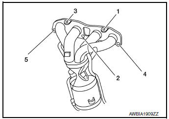
- Cylinder head
- Exhaust manifold and three way catalyst gasket
- Exhaust manifold cover (upper)
- Exhaust manifold and three way catalyst
- Exhaust manifold cover (lower front)
- Exhaust manifold cover (lower rear)
- Air fuel ratio (A/F) sensor 1
Removal and Installation
REMOVAL
- Disconnect battery negative terminal.
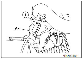
- Remove A/C line bracket bolt (A).

- Remove engine under cover. Refer to EXT-37, "ENGINE UNDER COVER : Removal and Installation".
- Remove the oil level gauge and oil level gauge guide. Refer to EM-92, "Exploded View".
- Remove harness ground wire bolt from generator bracket.
- Disconnect harness connector from air fuel ratio (A/F) sensor 1.
- Remove the air fuel ratio (A/F) sensor 1 (1) using Tool (A), (if necessary).
Tool number : KV10117100 (J-36471-A)
CAUTION:
- Be careful not to damage air fuel ratio (A/F) sensor.
- Discard any air fuel ratio (A/F) sensor which has been dropped from a height of more than 0.5 m (19.7 in) onto a hard surface such as a concrete floor; replace with a new one.
- Detach front exhaust tube from exhaust manifold and three way catalyst. Discard the gasket. Refer to EM-29, "Exploded View".
- Remove the exhaust manifold cover (upper).
- Loosen the exhaust manifold and three way catalyst nuts in the reverse order as shown.
- Remove exhaust manifold and three way catalyst.
- Remove the exhaust manifold cover (lower front) (if necessary).
- . Remove the exhaust manifold cover (lower rear) (if necessary).
INSPECTION AFTER REMOVAL
Surface Distortion
- Check the flatness of exhaust manifold and three way catalyst
using suitable tools (A/B).
NOTE: Place the suitable tool (A) diagonally and measure in several locations.
Limit : 0.3 mm (0.012 in)

INSTALLATION
Exhaust Manifold
Installation is in the reverse order of removal.
CAUTION:
- Do not reuse an exhaust manifold cover which has been dropped.
- Be careful not to deform exhaust manifold covers.
- Install studs in cylinder head studs and exhaust manifold and
three way catalyst (if removed). Then
tighten to specification.
CAUTION: Do not reuse cylinder head or exhaust manifold studs.
- Install the exhaust manifold and exhaust manifold and three way
catalyst gasket. Then tighten the nuts to specification in the
numerical order shown.
CAUTION: Do not reuse exhaust manifold and three way catalyst gasket.

- Install the air fuel ratio (A/F) sensor 1 (1) using Tool (A) and tighten to specification.
Tool number : KV10117100 (J-36471-A)
CAUTION:
- Be careful not to damage air fuel ratio (A/F) sensor.
- Discard any air fuel ratio (A/F) sensor which has been dropped from a height of more than 0.5 m (19.7 in) onto a hard surface such as a concrete floor; replace with a new one.
- Do not over-tighten the air fuel ratio (A/F) sensor 1. Doing so may cause damage to the air fuel ratio (A/F) sensor 1, resulting in a malfunction and the MIL coming on.

 Intake manifold
Exploded View
Intake manifold
Intake manifold gasket
Electirc throttle control actuator O-ring
Electric throttle control actuator
Removal and Installation
REMOVAL ...
 Oil pan and oil strainer
Exploded View
Oil pan, upper
Oil filter
Front cover
O-ring
Oil strainer
Oil pan, lower
Washer
Drain plug
O-ring
Oil level gaug ...
Other materials:
ECU diagnosis information
EPS CONTROL UNIT
Reference Value
VALUES ON THE DIAGNOSIS TOOL
CAUTION:
The output signal indicates the EPS control unit calculation data. The normal
values will be displayed
even in the event that the output circuit (harness) is open.
NOTE:
The following table includes information (items) ...
Wiring diagram
REAR WINDOW DEFOGGER SYSTEM
Wiring Diagram
...
Precaution
Precaution for Supplemental Restraint System (SRS) "AIR BAG" and "SEAT
BELT
PRE-TENSIONER"
The Supplemental Restraint System such as “AIR BAG” and “SEAT BELT
PRE-TENSIONER”, used along
with a front seat belt, helps to reduce the risk or severity of injury to the
...
