Nissan Rogue Service Manual: DTC/circuit diagnosis
POWER SUPPLY AND GROUND CIRCUIT
AUDIO UNIT
AUDIO UNIT : Diagnosis Procedure
Regarding Wiring Diagram information, refer to AV-27, "Wiring Diagram".
1.CHECK FUSE
Check that the following fuses are not blown.

Are the fuses blown? YES >> Replace the blown fuse after repairing the affected circuit.
NO >> GO TO 2.
2.CHECK POWER SUPPLY CIRCUIT
- Turn ignition switch OFF.
- Disconnect audio unit connector M83.
- Check voltage between audio unit connector M83 and ground.
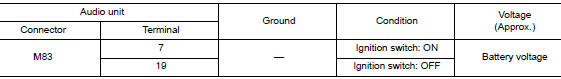
Is the inspection result normal? YES >> GO TO 3.
NO >> Repair or replace harness or connectors.
3.CHECK GROUND CIRCUIT
- Turn ignition switch OFF.
- Disconnect audio unit connector M87.
- Check continuity between audio unit connectors and ground.

Is the inspection result normal? YES >> Inspection End.
NO >> Repair or replace harness or connectors.
FRONT TWEETER
Diagnosis Procedure
Regarding Wiring Diagram information, refer to AV-27, "Wiring Diagram".
1.CONNECTOR CHECK
Check the audio unit and speaker connectors for the following:
- Proper connection
- Damage
- Disconnected or loose terminals
Is the inspection result normal? YES >> GO TO 2.
NO >> Repair the terminals or connectors.
2.CHECK FRONT TWEETER SIGNAL CIRCUIT CONTINUITY
- Disconnect audio unit connector M83 and suspect front tweeter connector.
- Check continuity between audio unit connector M83 and suspect front tweeter connector.

- Check continuity between audio unit connector M83 and ground.

Is the inspection result normal? YES >> GO TO 3.
NO >> Repair or replace harness or connectors.
3.CHECK FRONT TWEETER SIGNAL
- Connect audio unit connector M83 and suspect front tweeter connector.
- Turn ignition switch to ON.
- Push audio unit POWER switch.
- Check signal between the terminals of audio unit connector M83.


Is the inspection result normal? YES >> Replace front tweeter. Refer to AV-66, "Removal and Installation".
NO >> Replace audio unit. Refer to AV-64, "Removal and Installation".
FRONT DOOR SPEAKER
Diagnosis Procedure
Regarding Wiring Diagram information, refer to AV-27, "Wiring Diagram".
1.CONNECTOR CHECK
Check the audio unit and speaker connectors for the following:
- Proper connection
- Damage
- Disconnected or loose terminals
Is the inspection result normal? YES >> GO TO 2.
NO >> Repair the terminals or connectors.
2.CHECK FRONT DOOR SPEAKER SIGNAL CIRCUIT CONTINUITY
- Disconnect audio unit connector M83 and suspect front door speaker connector.
- Check continuity between audio unit connector M83 and suspect front door speaker connector.

- Check continuity between audio unit connector M83 and ground.

Is the inspection result normal? YES >> GO TO 3.
NO >> Repair or replace harness or connectors.
3.CHECK FRONT DOOR SPEAKER SIGNAL
- Connect audio unit connector M83 and suspect front door speaker connector.
- Turn ignition switch to ON.
- Push audio unit POWER switch.
- Check signal between the terminals of audio unit connector M83.

Is the inspection result normal? YES >> Replace front door speaker. Refer to AV-67, "Removal and Installation".
NO >> Replace audio unit. Refer to AV-64, "Removal and Installation".
REAR DOOR SPEAKER
Diagnosis Procedure
Regarding Wiring Diagram information, refer to AV-27, "Wiring Diagram".
1.CONNECTOR CHECK
Check the audio unit and speaker connectors for the following:
- Proper connection
- Damage
- Disconnected or loose terminals
Is the inspection result normal? YES >> GO TO 2.
NO >> Repair the terminals or connectors.
2.CHECK REAR DOOR SPEAKER SIGNAL CIRCUIT CONTINUITY
- Disconnect audio unit connector M83 and suspect rear door speaker connector.
- Check continuity between audio unit connector M83 and suspect rear door speaker connector.

- Check continuity between audio unit connector M83 and ground.

Is the inspection result normal? YES >> GO TO 3.
NO >> Repair or replace harness or connectors.
3.CHECK REAR DOOR SPEAKER SIGNAL
- Connect audio unit connector M83 and suspect rear door speaker connector.
- Turn ignition switch to ON.
- Push audio unit POWER switch.
- Check signal between the terminals of audio unit connector M83.


Is the inspection result normal? YES >> Replace rear door speaker. Refer to AV-68, "Removal and Installation".
NO >> Replace audio unit. Refer to AV-64, "Removal and Installation".
REAR VIEW CAMERA IMAGE SIGNAL CIRCUIT
Diagnosis Procedure
Regarding Wiring Diagram information, refer to AV-27, "Wiring Diagram".
1.CHECK REVERSE INPUT SIGNAL
- Turn ignition switch ON.
- Shift the selector lever to R (reverse).
- Check voltage between audio unit connector M87 and ground.

Is inspection result normal? YES >> GO TO 2.
NO >> Repair or replace harness or connectors.
2.CHECK CAMERA POWER SUPPLY CIRCUIT CONTINUITY
- Turn ignition switch OFF.
- Disconnect audio unit connector M87 and rear view camera connector.
- Check continuity between audio unit connector M87 and rear view camera connector D504.

- Check continuity between audio unit connector M87 and ground.

Is inspection result normal? YES >> GO TO 3.
NO >> Repair or replace harness or connectors.
3.CHECK CAMERA POWER SUPPLY VOLTAGE
- Connect audio unit connector M87 and rear view camera connector.
- Turn ignition switch ON.
- Shift the selector lever to R (reverse).
- Check voltage between audio unit connector M87 and ground.

Is inspection result normal? YES >> GO TO 4.
NO >> Replace audio unit. Refer to AV-64, "Removal and Installation".
4.CHECK CAMERA IMAGE SIGNAL CIRCUIT CONTINUITY
- Turn ignition switch OFF.
- Disconnect audio unit connector M87 and rear view camera connector.
- Check continuity between audio unit connector M87 and rear view camera connector D504.

- Check continuity between audio unit connector M87 and ground.

Is inspection result normal? YES >> GO TO 5.
NO >> Repair or replace harness or connectors.
5.CHECK CAMERA GROUND CIRCUIT CONTINUITY
Check continuity between audio unit connector M87 and rear view camera connector D504.

Is inspection result normal? YES >> GO TO 6.
NO >> Repair or replace harness or connectors.
6.CHECK CAMERA IMAGE SIGNAL
- Connect audio unit connector M87 and rear view camera connector.
- Turn ignition switch ON.
- Shift the selector lever to R (reverse).
- Check signal between audio unit connector M87 and ground.

Is inspection result normal? YES >> Replace audio unit. Refer to AV-64, "Removal and Installation".
NO >> Replace rear view camera. Refer to AV-71, "Removal and Installation".
MICROPHONE SIGNAL CIRCUIT
Diagnosis Procedure
Regarding Wiring Diagram information, refer to AV-27, "Wiring Diagram".
1.CHECK HARNESS BETWEEN AUDIO UNIT AND MICROPHONE
- Turn ignition switch OFF.
- Disconnect audio unit connector M87 and microphone connector R8.
- Check continuity between audio unit connector M87 and microphone connector R8.

- Check continuity between audio unit connector M87 and ground.

Is the inspection result normal? YES >> GO TO 2.
NO >> Repair harness or connectors.
2.CHECK MICROPHONE POWER SUPPLY
- Connect audio unit connector M87 and microphone connector R8.
- Turn ignition switch ON.
- Check voltage between microphone connector R8 and ground.

Is the inspection result normal? YES >> GO TO 3.
NO >> Replace audio unit. Refer to AV-64, "Removal and Installation".
3.CHECK MICROPHONE SIGNAL
Check signal between terminals of audio unit connector M87.

Is the inspection result normal? YES >> Replace audio unit. Refer to AV-64, "Removal and Installation".
NO >> Replace microphone. Refer to AV-70, "Removal and Installation".
STEERING SWITCH
Diagnosis Procedure
Regarding Wiring Diagram information, refer to AV-27, "Wiring Diagram".
1.CHECK STEERING WHEEL AUDIO CONTROL SWITCH RESISTANCE
- Turn ignition switch OFF.
- Disconnect combination switch connector M90
- Check resistance between the terminals of combination switch connector M90.

Is the inspection result normal? YES >> GO TO 2.
NO >> Replace steering switches. Refer to AV-65, "Removal and Installation".
2.CHECK HARNESS BETWEEN COMBINATION METER AND COMBINATION SWITCH
- Disconnect combination meter connector M76 and combination switch connector M30.
- Check continuity between combination meter connector M76 and combination switch connector M30.

- Check continuity between combination meter connector M76 and ground.

Is the inspection result normal?
YES >> GO TO 3.
NO >> Repair or replace harness or connectors.
3.CHECK COMBINATION SWITCH
Check continuity between combination switch connectors M90 and M30.
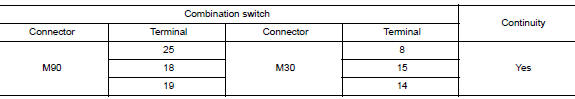
Is the inspection result normal? YES >> GO TO 4.
NO >> Replace spiral cable. Refer to SR-15, "Removal and Installation".
4.CHECK HARNESS BETWEEN COMBINATION METER AND AUDIO UNIT
- Disconnect combination meter connector M77 and audio unit connector M87.
- Check continuity between combination meter connector M77 and audio unit connector M87.

- Check continuity between combination meter connector M77 and ground.

Is the inspection result normal? YES >> Replace audio unit. Refer to AV-64, "Removal and Installation".
NO >> Repair or replace harness or connectors.
USB CONNECTOR
Diagnosis Procedure
Regarding Wiring Diagram information, refer to AV-27, "Wiring Diagram".
1.CHECK USB INTERFACE HARNESS CONTINUITY
- Turn ignition switch OFF.
- Disconnect audio unit connector M121 and USB interface connector M89.
- Check continuity between audio unit connector M121 and USB interface connector M89.

- Check continuity between audio unit connector M121 and ground.

Is the inspection result normal? YES >> Replace the USB interface. Refer to AV-69, "Removal and Installation".
NO >> Repair or replace harness or connectors.
AUXILIARY INPUT JACK
Diagnosis Procedure
Regarding Wiring Diagram information, refer to AV-27, "Wiring Diagram".
1.CHECK AUX JACK HARNESS CONTINUITY
- Turn ignition switch OFF.
- Disconnect audio control unit connector M88 and AUX in jack connector M104.
- Check continuity between audio control unit connector M88 and AUX in jack connector M104.

- Check continuity between audio control unit connector M88 and ground.

Is the inspection result normal? YES >> Replace the AUX in jack. Refer to AV-69, "Removal and Installation".
NO >> Repair or replace harness or connectors.
 Basic inspection
DIAGNOSIS AND REPAIR WORKFLOW
Work Flow
OVERALL SEQUENCE
DETAILED FLOW
1.GET INFORMATION FOR SYMPTOM
Get detailed information from the customer about the symptom (the condition
and the envi ...
 Symptom diagnosis
AUDIO SYSTEM
Symptom Table
RELATED TO AUDIO
Symptoms
Check items
Probable malfunction location
The disk cannot be removed
Audio unit
Malfunction in audio uni ...
Other materials:
Meter system
Wiring diagram
...
Removal and installation
FRONT WHEEL HUB
Exploded View
Disc brake rotor
Nut retainer
Cotter pin
Wheel stud
Steering knuckle
Splash guard
Wheel hub and bearing
Wheel hub lock nut
Removal and Installation
REMOVAL
Remove front wheel and tire using power tool. Refe ...
Diagnosis system (BCM) (with intelligent key system)
COMMON ITEM
COMMON ITEM : CONSULT Function (BCM - COMMON ITEM)
APPLICATION ITEM
CONSULT performs the following functions via CAN communication with BCM.
Direct Diagnostic Mode
Description
Ecu Identification
The BCM part number is displayed.
Self Diagnostic ...
