Nissan Rogue Service Manual: Diagnosis and repair work flow
Work Flow
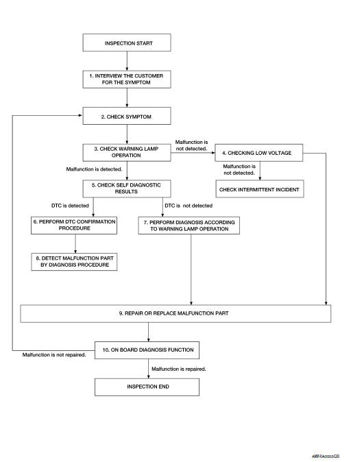
OVERALL SEQUENCE
DETAILED FLOW
1.INTERVIEW THE CUSTOMER FOR THE SYMPTOM
Interview the customer for the symptom (the condition and the environment when the incident/malfunction occurs).
>> GO TO 2.
2.CHECK SYMPTOM
Check the symptom from the customer information.
>> GO TO 3.
3.CHECK WARNING LAMP OPERATION
Check air bag warning lamp operation in the user mode.
Are any malfunction detected? YES >> GO TO 5.
NO >> GO TO 4.
4.CHECK LOW VOLTAGE
Check low voltage with CONSULT.
Are any malfunction detected? YES >> GO TO 9.
NO >> Check intermittent incident. Refer to GI-41, "Intermittent Incident".
5.CHECK SELF DIAGNOSTIC RESULTS
Check self diagnostic result with CONSULT or diagnosis mode.
If it is impossible to switch to diagnosis mode, follow the same procedure that DTC is not detected.
NOTE: Perform the following procedure if DTC is detected.
- Record DTC (Print them out with CONSULT.)
- Erase self diagnostic result.
- Study the relationship between the malfunction that DTC or air bag warning lamp indicates and the symptom that the customer describes.
- Check related service bulletins for information.
Is DTC detected? YES >> GO TO 6.
NO >> GO TO 7.
6.PERFORM DTC CONFIRMATION PROCEDURE
Perform DTC CONFIRMATION PROCEDURE for the DTC.
>> GO TO 8.
7.PERFORM DIAGNOSIS ACCORDING TO WARNING LAMP OPERATION
- Check air bag warning lamp operation in the user mode.
- Perform Diagnosis Procedure for the air bag warning lamp operation.
>> GO TO 9.
8.DETECT MALFUNCTIONING PART BY DIAGNOSTIC PROCEDURE
Inspect according to Diagnostic Procedure of the DTC.
>> GO TO 9.
9.REPAIR OR REPLACE THE MALFUNCTION PART
Repair or replace the malfunctioning part.
>> GO TO 10.
10.ON BOARD DIAGNOSIS FUNCTION
Check self diagnostic result and air bag warning lamp operation in the user mode.
Is the malfunction repaired? YES >> Inspection End.
NO >> GO TO 2.
 Basic inspection
...
 Inspection and adjustment
ADDITIONAL SERVICE WHEN REPLACING CONTROL UNIT
ADDITIONAL SERVICE WHEN REPLACING CONTROL UNIT : Description
When replacing the occupant classification system control unit, perform
zero point r ...
Other materials:
Symptom diagnosis
CVT CONTROL SYSTEM
Symptom Table
The diagnosis item number indicates the order of check. Start checking
in the order from 1.
Perform diagnoses of symptom table 1 before symptom table 2.
Symptom Table 1
Symptom Table 2
...
U1000 CAN COMM circuit
Description
CAN (Controller Area Network) is a serial communication line for real-time
application. It is an on-vehicle multiplex
communication line with high data communication speed and excellent malfunction
detection ability.
Many electronic control units are equipped onto a vehicle, and ...
Wiring diagram
MOONROOF SYSTEM
Wiring Diagram
...
